


 Topic Options
 iamalexis wrote:
Copyright © 1998
Cadman Enterprises Ltd
Welcome to the Graham Slee Audio Products Owners Forum  Open to all owners plus those contemplating the purchase of a Graham Slee HiFi System Components audio product and wishing to use this forum's loaner program: join here (Rules on posting can be found here) This website along with trade marks Graham Slee and HiFi System Components are owned by Cadman Enterprises Ltd |
Hints For Novo Kit Assembly |
Post Reply 
|
Page 123 4> |
| Author | |
iamalexis 
Senior Member 

Joined: 07 Feb 2009 Location: London Status: Offline Points: 119 |
 Post Options Post Options
") Thanks(0) Thanks(0)
 Quote Reply Quote Reply
 Topic: Hints For Novo Kit Assembly Topic: Hints For Novo Kit AssemblyPosted: 11 Mar 2009 at 12:42pm |
|
I will be assembling my kit over the weekend. I have some soldering skills/experience and was hoping to get some tips from those who have completed the kit and those with a lot of experience in soldering and electronics.
Alexis |
|
 |
|
|
Graham Slee
Admin Group 

Retired Joined: 11 Jan 2008 Location: South Yorkshire Status: Offline Points: 16314 |
Post Options
Thanks(0)
Quote Reply
Posted: 11 Mar 2009 at 9:27pm |
|
Hi Alexis,
Looking forward to your experiences Graham |
|
|
That none should be able to park up and enjoy the view without a smartphone and the knowledge in how to use apps
|
|
|
|
|
iamalexis
Senior Member
Joined: 07 Feb 2009 Location: London Status: Offline Points: 119 |
Post Options
Thanks(0)
Quote Reply
Posted: 15 Mar 2009 at 8:15pm |
|
for anyone interested this is how far i have got after spending approximately 6 hours (at a nice gentle pace) on the novo kit...
i have everything finished except for the testing and fitting the lid on the case (very easy), that is if it all works ok 
i just did a quick test by plugging in the psu to see if anything smoked or started burning but it seemed to be ok. i now need to do the test with the multi-meter as outlined in the manual. until now the only soldering i have done has been wiring up various audio leads, mainly jacks and xlrs, along with soldering a couple of simple kits from maplins. also i have a very basic understanding of electronics. i will give more details about my time on this and how i found it if anyone is interested, but first i need to make sure it is working! here are some pictures of my handy work..  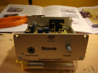 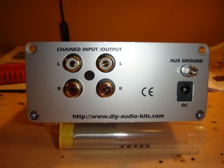
|
|
|
|
|
iamalexis
Senior Member
Joined: 07 Feb 2009 Location: London Status: Offline Points: 119 |
Post Options
Thanks(0)
Quote Reply
Posted: 15 Mar 2009 at 8:52pm |
|
ok so i have tested the various voltages show around the circuit diagram and they were all correct and guess what...it worked

i have had a quick listen and it sounds wonderful. so the lid is on, i now just need to stick the feet on to the bottom of the case and get it properly hooked up for an evening of listening (well deserved i feel!). as i mentioned in my last post i'm happy to share my experiences in more detail if anyone is interested. it's worth mentioning the main thing for me was taking my time and double checking everything; components in the correct place/correct way round, no dry joints etc. and then checking it all again before powering. i must say i enjoyed it very much and i'm ready for the psu1 kit now! one last picture for you... 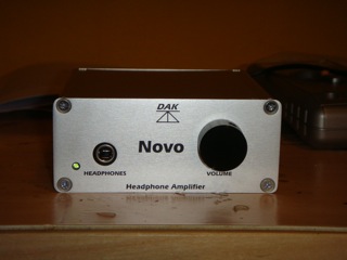
|
|
|
|
|
Graham Slee
Admin Group
Retired Joined: 11 Jan 2008 Location: South Yorkshire Status: Offline Points: 16314 |
Post Options
Thanks(0)
Quote Reply
Posted: 15 Mar 2009 at 10:58pm |
I can definitely say that quite a lot of people are interested, even if they're not yet members here. By the way - WELL DONE! |
|
|
That none should be able to park up and enjoy the view without a smartphone and the knowledge in how to use apps
|
|
|
|
|
Jitter
New Member 
Joined: 16 Feb 2009 Location: SE England Status: Offline Points: 38 |
Post Options
Thanks(0)
Quote Reply
Posted: 16 Mar 2009 at 10:02am |
|
as i mentioned in my last post i'm happy to share my experiences in more detail if anyone is interested....
I certainly would be very interested
|
|
|
...... and that's my opinion, take or leave it
|
|
|
|
|
ajb
New Member
Joined: 18 Mar 2009 Status: Offline Points: 1 |
Post Options
Thanks(0)
Quote Reply
Posted: 18 Mar 2009 at 10:46am |
|
I received and built a novo kit yesterday evening. An excellent kit
and the the instructions are well done. I regularly design and build my own stuff (digital, so I'm in awe of Graham's analogue expertise of course) therefore my experiences may not be the best to share but, for what they're worth, here are a few hints. The manual doesn't have a "what you'll need' section, which is fair enough for the group the kit is aimed at. I ended up using a 15W iron with 0.7mm solder (but used 1.2mm solder for the large tags), a pair of side-cutters, a metal hacksaw, small metal file, metric ruler, cross-head screwdriver bits and small flat-head screwdriver (for the pot control). Also a small hammer and metal punch (to help make electrical contact with the case as described in the manual - but people may be able to use other things they have to hand at that point). A solder-sucker may also be useful in case of mistakes. I would say that a multimeter is essential unless you have perfect eyesight (for resistor values) and are feeling particularly brave. With the resistors Graham supplies I'm sure there is no problem bending the resistor leads flush with the body so they lay 'tight' to the board. However, in the ancient days there was a nasty tendency for them to snap off if you did so. So, purely from force of habit and fear, I bent them a nails-width away the body. This had them standing very slightly proud of the surface. I've always done that anyway to allow air circulation and prevent hot-spots on the components (not important for this design as there's only the tiniest heat to dissipate). Before soldering in the pot and the LED, but after soldering in the phono jack, it is best to bend the LED leads as suggested and then, with the LED and pot in place, offer up the front panel. This allows you to see how far above the board surface the LED leads need to be and also to mark the pot spindle for length. You can then attack the pot spindle with a hacksaw and file down the sharp edges. I chopped off the anti-rotation spigot with side-cutters rather than use the pliers method in the manual - it was just easier do so in my case. Then solder the LED and pot in. The novo does sound good but I'll be leaving it to burn-in for a good while. Fortunately there's a Solo MC to listen to here while it does so. Alan |
|
|
|
|
Post Reply
|
Page 123 4> |
 Tweet
Tweet
|
| Forum Jump | Forum Permissions You cannot post new topics in this forum You cannot reply to topics in this forum You cannot delete your posts in this forum You cannot edit your posts in this forum You cannot create polls in this forum You cannot vote in polls in this forum |
Forum Software by Web Wiz Forums® version 12.01
Copyright ©2001-2018 Web Wiz Ltd.
This page was generated in 0.070 seconds.
Copyright ©2001-2018 Web Wiz Ltd.
This page was generated in 0.070 seconds.