Hints For Novo Kit Assembly
Printed From: Graham Slee Hifi System Components
Category: DIY AUDIO
Forum Name: DIY Audio questions and answers
Forum Description: www.diy-audio-kits.com ... superb audio kits for experienced constructors
URL: https://www.hifisystemcomponents.com/forum/forum_posts.asp?TID=406
Printed Date: 27 Mar 2026 at 2:12am
Software Version: Web Wiz Forums 12.01 - http://www.webwizforums.com
Topic: Hints For Novo Kit Assembly
Posted By: iamalexis
Subject: Hints For Novo Kit Assembly
Date Posted: 11 Mar 2009 at 12:42pm
|
I will be assembling my kit over the weekend. I have some soldering skills/experience and was hoping to get some tips from those who have completed the kit and those with a lot of experience in soldering and electronics.
Alexis |
Replies:
Posted By: Graham Slee
Date Posted: 11 Mar 2009 at 9:27pm
|
Hi Alexis, Looking forward to your experiences Graham ------------- That none should be able to park up and enjoy the view without a smartphone and the knowledge in how to use apps |
Posted By: iamalexis
Date Posted: 15 Mar 2009 at 8:15pm
|
for anyone interested this is how far i have got after spending approximately 6 hours (at a nice gentle pace) on the novo kit...
i have everything finished except for the testing and fitting the lid on the case (very easy), that is if it all works ok 
i just did a quick test by plugging in the psu to see if anything smoked or started burning but it seemed to be ok. i now need to do the test with the multi-meter as outlined in the manual. until now the only soldering i have done has been wiring up various audio leads, mainly jacks and xlrs, along with soldering a couple of simple kits from maplins. also i have a very basic understanding of electronics. i will give more details about my time on this and how i found it if anyone is interested, but first i need to make sure it is working! here are some pictures of my handy work..  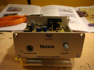 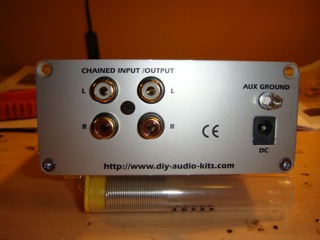
|
Posted By: iamalexis
Date Posted: 15 Mar 2009 at 8:52pm
ok so i have tested the various voltages show around the circuit diagram and they were all correct and guess what...it worked 
i have had a quick listen and it sounds wonderful. so the lid is on, i now just need to stick the feet on to the bottom of the case and get it properly hooked up for an evening of listening (well deserved i feel!). as i mentioned in my last post i'm happy to share my experiences in more detail if anyone is interested. it's worth mentioning the main thing for me was taking my time and double checking everything; components in the correct place/correct way round, no dry joints etc. and then checking it all again before powering. i must say i enjoyed it very much and i'm ready for the psu1 kit now! one last picture for you... 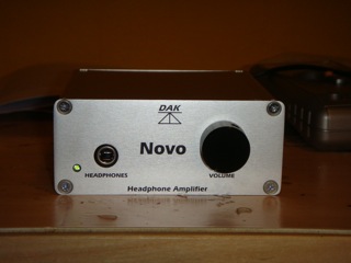
|
Posted By: Graham Slee
Date Posted: 15 Mar 2009 at 10:58pm
I can definitely say that quite a lot of people are interested, even if they're not yet members here. By the way - WELL DONE! ------------- That none should be able to park up and enjoy the view without a smartphone and the knowledge in how to use apps |
 iamalexis wrote:
Posted By: Jitter
Date Posted: 16 Mar 2009 at 10:02am
|
as i mentioned in my last post i'm happy to share my experiences in more detail if anyone is interested.... I certainly would be very interested ------------- ...... and that's my opinion, take or leave it |
Posted By: ajb
Date Posted: 18 Mar 2009 at 10:46am
|
I received and built a novo kit yesterday evening. An excellent kit and the the instructions are well done. I regularly design and build my own stuff (digital, so I'm in awe of Graham's analogue expertise of course) therefore my experiences may not be the best to share but, for what they're worth, here are a few hints. The manual doesn't have a "what you'll need' section, which is fair enough for the group the kit is aimed at. I ended up using a 15W iron with 0.7mm solder (but used 1.2mm solder for the large tags), a pair of side-cutters, a metal hacksaw, small metal file, metric ruler, cross-head screwdriver bits and small flat-head screwdriver (for the pot control). Also a small hammer and metal punch (to help make electrical contact with the case as described in the manual - but people may be able to use other things they have to hand at that point). A solder-sucker may also be useful in case of mistakes. I would say that a multimeter is essential unless you have perfect eyesight (for resistor values) and are feeling particularly brave. With the resistors Graham supplies I'm sure there is no problem bending the resistor leads flush with the body so they lay 'tight' to the board. However, in the ancient days there was a nasty tendency for them to snap off if you did so. So, purely from force of habit and fear, I bent them a nails-width away the body. This had them standing very slightly proud of the surface. I've always done that anyway to allow air circulation and prevent hot-spots on the components (not important for this design as there's only the tiniest heat to dissipate). Before soldering in the pot and the LED, but after soldering in the phono jack, it is best to bend the LED leads as suggested and then, with the LED and pot in place, offer up the front panel. This allows you to see how far above the board surface the LED leads need to be and also to mark the pot spindle for length. You can then attack the pot spindle with a hacksaw and file down the sharp edges. I chopped off the anti-rotation spigot with side-cutters rather than use the pliers method in the manual - it was just easier do so in my case. Then solder the LED and pot in. The novo does sound good but I'll be leaving it to burn-in for a good while. Fortunately there's a Solo MC to listen to here while it does so. Alan |
Posted By: iamalexis
Date Posted: 18 Mar 2009 at 8:52pm
|
here is how i got on. i'm no expert in this field so please bare this in mind. it's my first "proper" kit and this isn't meant to be a my how to/hints, but a summary of my experience in a bit of detail. i echo alan's comments about the excellent kit and instructions. i think a "what you need" section in the manual would be useful. i had most of what i needed but had to borrow the hacksaw and file from a neighbour.
i took my time building this kit and feel that it paid off in the end. it worked first time which was a surprise to me and meant i didn't have to do any fault finding! i started with soldering the resistors in place as outlined in the manual. i don't know one resistor from the next so i used the table in the manual to work out the value of the resistor and then the circuit diagram to show me which resistor went where. i then doubled checked this with the photo of the pcb in the manual to make sure it "looked" right. i nearly got caught out putting the wrong resistor in the wrong place as some look very similar. (maybe i should have measured them with a multi-meter?!). with lots of double checking i spotted my mistake before soldering them in place. once they were all in i soldered in the diodes. it was clear from the picture what way round they go. with all of them in place and checking again they were correct, i checked for any dry joints and moved on to the next stage, transistors and capacitors. the tip in the manual for soldering transistor pins, (so that heat builds up towards the collector terminal) was useful as i didn't know this. however i did have to check which pin is what in my beginner electronics book! the printing on the pcb and the photo make it clear what way round they go. with the capacitors i knew from my maplins kit the short leg on a capacitor is negative (correct me if i'm wrong) so it was easy to follow the polarity on the pcb. i think it is also labelled on the capacitor body (i told you i'm a novice!). i chose to solder all the capacitors in place before moving onto the next stage, although i think the manual takes you through it in a slightly different order. one thing i was worried about was heating up components too much and damaging them or the board-fortunately this didn't happen. i was constantly blowing on joints and the components once they were soldered to cool them down! i'm sure this isn't necessary but it made me feel better! the next stage was quite simple, soldering the dc socket and phones jack on to the board. the manual takes you through what you need to watch out for. the potentiometer/volume pot went on next and again i followed the instructions as to how to prepare it and make sure it goes on right. alan's tip in the previous post regarding the LED and volume pot makes a lot of sense now i have completed the kit but i didn't think of it at the time! the manual does give you details on the length to cut the spindle if fitting the case supplied by graham slee, and also where to bend the LED so it fits correctly. i think alan's tip if a good way of getting it exact without too much hassle. the next step is simple although i was a little worried about it-soldering a length of tinned copper wire (supplied in kit) between a tag on the pot and the pcb. i found this to be no problem. i think as it was different from soldering components to the board i worried myself unnecessarily. i then fitted on the phono block and soldered this in place, nice and easy. after that there are only a few things left to do before completing the "electronic" side of the assembly. i was a little worried about having to run a flying lead between a resistor and capacitor across the back of the pcb (it sounds more complicated than it is) but again this proved ok, just make sure you don't cut the insulated wire (also provided in the kit) too short! i then slotted the finished board into the case, which is simple, and made the ground connections. i powered her up and tested the various voltages around the circuit using a multimeter as outlined in the manual. i have hardly used a multi-meter before but i found it straight forward. all the voltage readings were good so i excitedly hooked it up to my system to have a listen! it sounded great and i felt very pleased with myself! overall i probably spent around 7 hours on the whole thing from start to finish. i took it at a nice leisurely pace. soldering all the resistors probably took the most time due to the amount of them (around 36 i think) and making sure i had the correct ones in the right place. there wasn't any point where i felt i didn't have any of the necessary skills. i took my time over it and felt very satisfied once i had completed it, especially as it worked a treat! so that was how i found it and i'm a very happy customer 
|
Posted By: mrarroyo
Date Posted: 19 Mar 2009 at 12:38am
|
Very nice summary, sure makes me want to try a hand at it. Thanks. ------------- Miguel |
Posted By: jonclancy
Date Posted: 19 Mar 2009 at 8:55am
|
Go on, Miguel!! |
Posted By: mrarroyo
Date Posted: 19 Mar 2009 at 10:28pm
|
I have been know to damage boards, so I am a bit hesitant. ------------- Miguel |
Posted By: Spirit
Date Posted: 21 Mar 2009 at 8:21am
|
Pfft... I think it'd be good for you Miguel ;)
------------- Buff II / D2000 |
Posted By: jonclancy
Date Posted: 22 Mar 2009 at 10:00pm
|
Perhaps I ought to go and knock on his door....... |
Posted By: mrarroyo
Date Posted: 23 Mar 2009 at 12:49am
|
Jon are you in Miami Beach Florida? ------------- Miguel |
Posted By: jonclancy
Date Posted: 23 Mar 2009 at 9:51am
| Nope, but occasionally I visit MIA on business and stay at South Beach..... |
Posted By: mrarroyo
Date Posted: 24 Mar 2009 at 1:01am
|
Ok, if you do let me know and we could go out for a beer or vino! ------------- Miguel |
Posted By: mrarroyo
Date Posted: 24 Mar 2009 at 2:08am
|
I just ordered the board kit! Graham I sent you a PM since I could not find the additional parts for 12 BP. Please send me a PayPal bill as per my PM. Thanks. ------------- Miguel |
Posted By: littletree76
Date Posted: 24 Mar 2009 at 7:33am
|
Graham,
I am thinking of assembling Novo full kit to work with my Cambridge Audio's DAC Magic and AKG 701 headphone. But I have following questions to clarify: Have the components in a kit gone through QA screening, testing and matching before packaging ? I wonder what to do when there is channel imbalance caused by unmatched components after assembly is completed. Is the Novo commercial version a better option as far as build quality assurance is concerned. What is the power/voltage/current specifications for the switching power supply unit ? I am thinking of sourcing a better one (in term of current capability and output noise/ripple) locally for output improvement. Once I received a switching power supply unit from UK similar to the one in Novo kit for my DAC. The power supply unit heated up easily even with light load because of poor energy conversion efficiency (not greener than linear power supply). Thanks in advance. |
Posted By: jonclancy
Date Posted: 24 Mar 2009 at 9:24am
|
Miguel,
Yes, that'll be great!! I'll drop you a line when I get my next visit. Well done for ordering your kit!! We'll have you over on the Dark Side before you know it!!
Jon
|
Posted By: Graham Slee
Date Posted: 24 Mar 2009 at 10:30am
Hi littletree and welcome to the community! Every single piece in the DAK Novo kit is the same spec as used in the commercial Novo. We don't believe in wasting time here at Graham Slee Projects Limited so we don't go in for "crank" designs that require trimming either before, during or after assembly: if the components have been put in the right place (and the right way round in the case of transistors, diodes, polarised capacitors and so on, and soldered properly) then no channel imbalance due to the electronics can exist. The potentiometer is therefore the deciding factor: this is sourced directly from an Alps Europe authorised distributor - we know a large franchised distributor sells Alps seconds for profit, so we don't go there for anything apart from solder tags. If a one in a million problem were to exist where a part was found faulty we guarantee to replace it. As for the power supply, I buy these from people I know, then I test them myself. It is rated 24 volts 0.75 amps, centre positive. I have three working constantly in my own system and the one that powers my Novo gets barely warm. Our components are all genuine branded items from Philips, Panasonic, Welwyn, Vishay, Alps, On-Semiconductor, etc. We would rather pay more and have the best reputation rather than penny-pinch - we find we profit more by having good measures. Going back to component matching for a moment: there are some who learn electronics professionally and there are some that dabble and have never had the experience of professional learning - people should be alarmed by this but they are not - they believe the dabblers because they are so convincing in their arguments, and to the non-electronic mind the false positives stack up. I have seen the dabblers designs - these are people who big themselves up but they are in reality very tiny. Proper electronics designs take into consideration the tolerances of components because all components are plus or minus some percentage away from their specified value. Take the op-amp for example: apart from laser zapping to minimise offset voltages to microscopic proportions for instrument usage, no other part of an op-amp is "hand matched" but in our findings, those which we use (in designs other than the Novo) are all within spec. That is what proper design is about. I hope this brings you more confidence in us. Best wishes, Graham ------------- That none should be able to park up and enjoy the view without a smartphone and the knowledge in how to use apps |
Posted By: mrarroyo
Date Posted: 24 Mar 2009 at 10:00pm
|
I also have read that components will drift when placed in service. So if before you install an electronic component you were to measure it and then you come back a month after being in service and you re-measure it the value will be different. ------------- Miguel |
Posted By: Graham Slee
Date Posted: 24 Mar 2009 at 11:38pm
|
Drift can be a problem in "simple" or "basic" designs where minimalist circuitry is involved because gain and bandwidth is very dependant on the few components (generally resistors) used. However, although circuits like the Novo look simple due to the "experienced hands" of an "old-timer" PCB designer, they have similarities to early modular opamps which are designed to be stable against component drift.  example of an early modular opamp The one pictured above is by GAP/R (later Teledyne) from 1963 and carbon resistors having the worst drift can be seen. Even so, the design was such that it would not have measurably drifted because of these. In the Novo we use metal film resistors whose drift is as little as 50 - 75 parts per million per year (0.005 - 0.0075%) once burnt-in, and 100 - 200 ppm/year from new. By careful component selection by which I mean buying the right parts from reputable manufacturers with a reputation to keep there should be no measurable drift, but as components settle performance improves over the normal and accepted burn-in period. ------------- That none should be able to park up and enjoy the view without a smartphone and the knowledge in how to use apps |
Posted By: littletree76
Date Posted: 25 Mar 2009 at 12:24am
|
Based on what I have read above from Graham, I suppose the Novo kit use quality discrete components with low tolerance and drift to contain variation in electrical parameters. Feedback and servo loops have been used as well to remove dependency on absolute values of components to further ensure the amplifier circuit will perform within designed tolerance and all measurable parameters meeting specifications throughout its life span ? Perhaps being built with discrete components instead of ICs helps in achieving this goal.
In this case, anyone with some basic soldering skill and understanding of electronic engineering should be able to assemble the kit and tweaking/adjustment after assemble is not necessary for it to work according to specifications. But consider the fact that I was struggling with soldering opamp in SOIC package onto Brown Dog SOIC-to-DIP adaptor recently in rolling opamp of portable headphoe amplifier, I might have to opt for commercial Novo (I studied electronic engineering about eighteen years ago). |
Posted By: mrarroyo
Date Posted: 25 Mar 2009 at 12:52pm
|
littletree76, I am all thumbs and I have burnt boards before. ------------- Miguel |
Posted By: jonclancy
Date Posted: 25 Apr 2009 at 6:01pm
| ...and how are you getting on with it, Miguel? |