


 Topic Options
 Ernie wrote:
Copyright © 1998
Cadman Enterprises Ltd
Welcome to the Graham Slee Audio Products Owners Forum  Open to all owners plus those contemplating the purchase of a Graham Slee HiFi System Components audio product and wishing to use this forum's loaner program: join here (Rules on posting can be found here) This website along with trade marks Graham Slee and HiFi System Components are owned by Cadman Enterprises Ltd |
Groove Runner Turntable Speed Control |
Post Reply 
|
Page <1 3456> |
| Author | |
Dave Friday 
Senior Member 
Joined: 07 Apr 2011 Location: Spain Status: Offline Points: 173 |
 Post Options Post Options
") Thanks(0) Thanks(0)
 Quote Reply Quote Reply
 Posted: 11 Oct 2018 at 10:55am Posted: 11 Oct 2018 at 10:55am |
|
Hi Graham,what's the distorted waveform ?
Ta.
|
|
|
lp12,oc9mk3,ca610p,krimson40watt pa,kef105.4
|
|
 |
|
|
Graham Slee
Admin Group 

Retired Joined: 11 Jan 2008 Location: South Yorkshire Status: Offline Points: 16314 |
Post Options
Thanks(0)
Quote Reply
Posted: 11 Oct 2018 at 11:12am |
|
Hi Barry, it's what comes out of the RP3 circuit. One winding gets voltage via a cap and resistor, the other gets it via the same cap, a different resistor and another capacitor. I did AC theory (for motors and stuff) a long time ago so I haven't a chance of working this one out
 . For normal 230V use I'm sure a 10k power resistor and a 0.22uF cap would do better . . For normal 230V use I'm sure a 10k power resistor and a 0.22uF cap would do better . |
|
|
That none should be able to park up and enjoy the view without a smartphone and the knowledge in how to use apps
|
|
|
|
|
Ernie
Senior Member
Joined: 23 Jan 2014 Location: Birmingham UK Status: Offline Points: 430 |
Post Options
Thanks(0)
Quote Reply
Posted: 11 Oct 2018 at 7:32pm |
|
Hi Graham,
That’s not a circuit I’ve seen before on one of these little motors.
|
|
|
There are 10 kinds of people. Those who understand binary and those who don't.
|
|
|
|
|
Graham Slee
Admin Group
Retired Joined: 11 Jan 2008 Location: South Yorkshire Status: Offline Points: 16314 |
Post Options
Thanks(0)
Quote Reply
Posted: 11 Oct 2018 at 8:48pm |
|
Do you mean the Rega circuit?
I have three instances of the circuit (can only find one right now - typical!) and here is a photo I just took of the board, showing the values indicated in my diagram. I'm quite fussy about getting my facts right in public, otherwise I'd be in dangerous territory, and I was employed in reverse engineering for part of my career, which I have to thank for at least some of my knowledge. 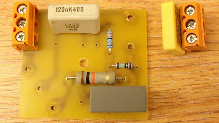 There is also a diagram on the internet which agrees, and that can be found here: https://www.stereo.net.au/forums/applications/core/interface/imageproxy/imageproxy.php?img=http://i204.photobucket.com/albums/bb317/floyd2_01/Rega%2520Motor/RegaMotorDriveSchematics1.jpg&key=f21eafd96e2db0bfa532786a3f2833adf133a6f51aee28b0f99b19932e7f500d The board image can also be found here: https://www.picclickimg.com/d/w1600/pict/222930888677_/Rega-Planar-2-turntable-motor-may-fit-Moth.jpg And here: https://en.wikipedia.org/wiki/Rega_Planar_3#/media/File:0081_motor_and_spindle.jpg |
|
|
That none should be able to park up and enjoy the view without a smartphone and the knowledge in how to use apps
|
|
|
|
|
Ernie
Senior Member
Joined: 23 Jan 2014 Location: Birmingham UK Status: Offline Points: 430 |
Post Options
Thanks(0)
Quote Reply
Posted: 11 Oct 2018 at 10:09pm |
|
Hi Graham,
If this was a decent sized motor I’d say you’ve got an odd order harmonic affecting it hence the dip in the waveform. It looks like Rega have added reactance to the circuit to try and control it when powered from the mains. The harmonic could be due to driving the magnetic circuit into saturation. I may have got my numbers wrong but the standard drive circuit for this motor looks the same as all the others a resistor and capacitor. May be worth trying this circuit rather than the Rega one as the transformer you’ve fitted won’t have the same impedance as the mains supply. Looking at the data sheet for the motor 9904-111-31104 (Farnell 147876) it just needs a 0.1uF cap between the windings.
Edited by Ernie - 11 Oct 2018 at 10:40pm |
|
|
There are 10 kinds of people. Those who understand binary and those who don't.
|
|
|
|
|
Graham Slee
Admin Group
Retired Joined: 11 Jan 2008 Location: South Yorkshire Status: Offline Points: 16314 |
Post Options
Thanks(0)
Quote Reply
Posted: 11 Oct 2018 at 10:44pm |
Obviously not, but then again it isn't so high as to cause all of what you see. I have been using the (R and C) circuit you refer to for most of the trials (first circuit previous page, a number of different permutations over close to a year) but have never witnessed any motor having an effect on the output impedance of the transformer or the waveforms. And that included wiring it in series which is higher impedance to obtain 220V, to drive a 3.6 watt motor which stressed the transformer near to its design limits (case gets a bit hot too). Also, the transformer was developed special for the job so doesn't exhibit the same limitations as a mains transformer in reverse. It runs significantly cooler too.
|
|
|
That none should be able to park up and enjoy the view without a smartphone and the knowledge in how to use apps
|
|
|
|
|
Graham Slee
Admin Group
Retired Joined: 11 Jan 2008 Location: South Yorkshire Status: Offline Points: 16314 |
Post Options
Thanks(0)
Quote Reply
Posted: 11 Oct 2018 at 10:53pm |
|
Re your edit, the added (series) resistor for higher frequency use is shown here: https://www.mclennan.co.uk/datasheet/1565 As 3/4 of its intended use is at 60 - 81 Hz I considered it a better choice than just having the 0.1uF capacitor. It also runs well at 50Hz, especially as the motor is operating on half intended voltage. Plus it will start and run at minimum output which is just below 90V. It is incredibly quiet in operation and starts up in the same time as a 31813. Also please understand that the Rega scope waveform was just an observation, and I only included the original circuit as part of the explanation that the Groove-Runner is able to drive the 230V version unmodified (at least the one I have), which might be a plus point to somebody contemplating a purchase.
Edited by Graham Slee - 11 Oct 2018 at 11:02pm |
|
|
That none should be able to park up and enjoy the view without a smartphone and the knowledge in how to use apps
|
|
|
|
|
Post Reply
|
Page <1 3456> |
 Tweet
Tweet
|
| Forum Jump | Forum Permissions You cannot post new topics in this forum You cannot reply to topics in this forum You cannot delete your posts in this forum You cannot edit your posts in this forum You cannot create polls in this forum You cannot vote in polls in this forum |
Forum Software by Web Wiz Forums® version 12.01
Copyright ©2001-2018 Web Wiz Ltd.
This page was generated in 0.063 seconds.
Copyright ©2001-2018 Web Wiz Ltd.
This page was generated in 0.063 seconds.