


 Topic Options
Copyright © 1998
Cadman Enterprises Ltd
Welcome to the Graham Slee Audio Products Owners Forum  Open to all owners plus those contemplating the purchase of a Graham Slee HiFi System Components audio product and wishing to use this forum's loaner program: join here (Rules on posting can be found here) This website along with trade marks Graham Slee and HiFi System Components are owned by Cadman Enterprises Ltd |
DIY Power Supply for Gram Amp 2 |
Post Reply 
|
Page 12> |
| Author | |
GrahamD 
New Member 
Joined: 13 Feb 2015 Location: Auckland NZ Status: Offline Points: 34 |
 Post Options Post Options
") Thanks(0) Thanks(0)
 Quote Reply Quote Reply
 Topic: DIY Power Supply for Gram Amp 2 Topic: DIY Power Supply for Gram Amp 2Posted: 17 Mar 2015 at 9:18am |
|
My Gram Amp Communicator came with the standard 'green' PSU. From comments on this forum it was clear a better more stable and powerful PSU would yield sonic improvements. However no one down here in NZ had anything available so I built up my own.
It uses a quality 240/24 volt transformer, diode rectifier set, followed by a LM317 voltage regulator and 4 1000uf caps. Once the regulator is adjusted with a trim pot to provide output of exactly 24 volts it is rock steady. Works great and is burning in the little amp as we speak. Cheers Graham |
|
 |
|
|
BAK
Senior Member 

Joined: 14 Mar 2010 Location: Kentucky, USA Status: Offline Points: 1831 |
Post Options
Thanks(0)
Quote Reply
Posted: 17 Mar 2015 at 2:18pm |
|
Hi GrahamD, Good job making a power supply. Most people are afraid of working with mains voltages.
Be sure to have a 0.5 amp fuse on the mains input for safety. For improved clarity, add a 10 ohm (5 watt, wirewound) resistor in series to the input to the rectifier and a 0.002 uF (100v) disc directly across the transformer secondary. After the rectifier, put a 0.1 uF (100v) ceramic disc across the input to the LM317. These added filter components strip away almost all the noise from the mains supply. The output voltage will be very stable with the LM317 regulator, it is one of my favorites. Be sure to put in the manufacturer recommended reverse biased diode across the output for large filter capacitors, it is described in the LM317 datasheets for National Semiconductors. As time passes, the trimmer potentiometer will be a weak link, replace with suitable 1% resistors if possible. Note: more than 1000 uF (100v) filter caps is overkill, and may be stressful on the LM317. Here to help, Bruce Edited by BAK - 18 Mar 2015 at 12:53pm |
|
|
Bruce
AT-14SA, Pickering XV-15, Hana EL, Technics SL-1600MK2, Lautus, Majestic DAC, Technics SH-8055 spectrum analyzer, Eminence Beta8A custom cabs; Proprius & Reflex M or C, Enjoy Life your way! |
|
|
|
|
JamesD
Senior Member

Joined: 05 Nov 2012 Location: Bolsover Status: Offline Points: 246 |
Post Options
Thanks(0)
Quote Reply
Posted: 17 Mar 2015 at 6:35pm |
|
Wouldn't the filter capacitors go before the LM317 rather than on it's output or am I missing something?
|
|
|
Aren't ears brilliant
|
|
|
|
|
BAK
Senior Member
Joined: 14 Mar 2010 Location: Kentucky, USA Status: Offline Points: 1831 |
Post Options
Thanks(0)
Quote Reply
Posted: 17 Mar 2015 at 8:12pm |
|
"It uses a quality 240/24 volt transformer, diode rectifier set, followed by a LM317 voltage regulator and 4 1000uf caps."
Your description led me to believe the 4 each, 1000uf caps, were on the output of the Lm317. If on the input (or before the regulator), no more than 100 to 330 uF would be required, 500 uF would be OK. The LM317 is so good at rejecting input voltage fluctuations, larger capacitors are not needed, but a 0.1 uF ceramic disc is a very fast capacitor needed to filter the RF and EMF noise on power lines. I would still use 330 to 500 uF on the final output, after the regulator, for stiffening the voltage for the varying current load. Still a reverse biased diode across the output for large filter capacitors is recommended. If you wish, I can send you a pdf file of the datasheet for the LM317. It completely covers the circuit design requirements and has example schematics. Another of National Semiconductors' design hints is to put a 10 uF, 50v cap across adjustment pin to ground for added noise reduction and stability. I have used this regulator in many designs. It has better noise and ripple reduction figures than a standard TO220 style LM7805, 7812, 7824...etc. Here to help, Bruce Edited by BAK - 18 Mar 2015 at 12:09pm |
|
|
Bruce
AT-14SA, Pickering XV-15, Hana EL, Technics SL-1600MK2, Lautus, Majestic DAC, Technics SH-8055 spectrum analyzer, Eminence Beta8A custom cabs; Proprius & Reflex M or C, Enjoy Life your way! |
|
|
|
|
Fatmangolf
Moderator Group 
Joined: 23 Dec 2009 Location: Middlesbrough Status: Offline Points: 9695 |
Post Options
Thanks(0)
Quote Reply
Posted: 17 Mar 2015 at 9:54pm |
|
I'm slightly late to the party and with the same advice as Bruce has given already. Happy listening Graham.
|
|
|
Jon
Open mind and ears whilst owning GSP Genera, Accession M, Accession MC, Elevator EXP, Solo ULDE, Proprius amps, Cusat50 cables, Lautus digital cable, Spatia cables and links, and a Majestic DAC. |
|
|
|
|
GrahamD
New Member
Joined: 13 Feb 2015 Location: Auckland NZ Status: Offline Points: 34 |
Post Options
Thanks(0)
Quote Reply
Posted: 18 Mar 2015 at 7:55am |
|
This is the circuit used ( sorry about the crappy drawing) which includes the reverse bias diodes not mentioned in my original brief description.
If you can provide any suggestions to further improve or modify it please feel free to offer them. Cheers Graham 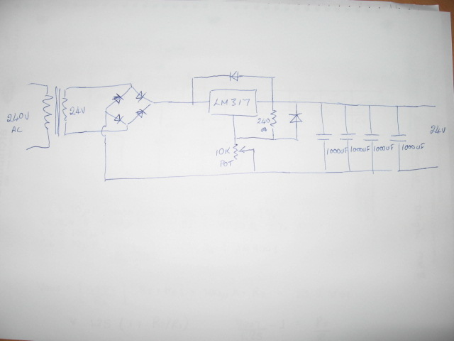
|
|
|
|
|
BAK
Senior Member
Joined: 14 Mar 2010 Location: Kentucky, USA Status: Offline Points: 1831 |
Post Options
Thanks(1)
Quote Reply
Posted: 18 Mar 2015 at 1:14pm |
|
HI GrahamD,
Be sure to have a 0.5 amp fuse on the mains input for safety, close to the mains entering the box... on 240v AC mains, it would be better to have one fuse on each leg of the mains. Move one of the 1000 uF electrolytics (minimum 50v, 100v would be better, even 75v) to before the regulator and put a 0.1 uF (100v) ceramic capacitor across it for RF noise rejection. If you have a 100 to 500 uF (again, minimum 50v, 100v would be better, even 75v) use that here. Larger value electrolytics are only needed for larger currents, anything too big will reduce the regulation. This filters the AC component of ripple going into the regulator so the regulator is able to regulate the DC better. The protection diodes are shown correctly placed. Keep only one 1000 uF on the output for stiffening. Here to help, Bruce |
|
|
Bruce
AT-14SA, Pickering XV-15, Hana EL, Technics SL-1600MK2, Lautus, Majestic DAC, Technics SH-8055 spectrum analyzer, Eminence Beta8A custom cabs; Proprius & Reflex M or C, Enjoy Life your way! |
|
|
|
|
Post Reply
|
Page 12> |
 Tweet
Tweet
|
| Forum Jump | Forum Permissions You cannot post new topics in this forum You cannot reply to topics in this forum You cannot delete your posts in this forum You cannot edit your posts in this forum You cannot create polls in this forum You cannot vote in polls in this forum |
Forum Software by Web Wiz Forums® version 12.01
Copyright ©2001-2018 Web Wiz Ltd.
This page was generated in 0.070 seconds.
Copyright ©2001-2018 Web Wiz Ltd.
This page was generated in 0.070 seconds.