Voyager dodge may help some DACs
Printed From: Graham Slee Hifi System Components
Category: DIY AUDIO
Forum Name: Graham's Wrinkles
Forum Description: My hints and tips on how to squeeze that little extra from an old
URL: https://www.hifisystemcomponents.com/forum/forum_posts.asp?TID=866
Printed Date: 27 Mar 2026 at 2:11am
Software Version: Web Wiz Forums 12.01 - http://www.webwizforums.com
Topic: Voyager dodge may help some DACs
Posted By: Graham Slee
Subject: Voyager dodge may help some DACs
Date Posted: 23 Apr 2010 at 1:53pm
|
The Voyager is an extremely stable amp with good phase and gain margins -
contour switch in or out. So what's been the problem with a handful of users having trouble when using the outputs of some DACs (don't ask me which - my memory doesn't stretch that far)? They report distortion at high volume levels. Maybe they're not trying to deafen themselves? Better to give them the benefit of the doubt... Using our "premium priced" SPICE simulator (because no audio test sets go beyond a few hundred kHz) the stock Voyager shows no distress, but there is a 6dB (approx) peak well into the MHz region - something quite common judging by simulations done on other manufacturers designs of the past. I'd have normally suspected instability with such a peak, but the phase plots showed everything being OK. If anything can explain this, it's a rapid change in phase around the same frequency, but it's nowhere near 90 degrees, never mind 180 degrees. It's an op-amp artifact where what it's doing is protecting its own stability by giving itself a gain boost. As no output should exist up there, then the input signal couldn't clip the rails - otherwise that could cause the distortion... Ah but! We have all read about DAC designers who feel output filtering unnecessary?! If this were to be the case, there would be the sampling frequency of at least 44.1kHz - more if oversampled? Not high enough, but the harmonics could be! If these extend to where the peak in the response is, then clipping could occur, causing audible problems further down the spectrum, possibly explaining the distortion this handful of users experience close to clip levels. The only way around this would be to curtail the amp's gain before it reaches the above mentioned peak, and here's a dodge to achieve it... 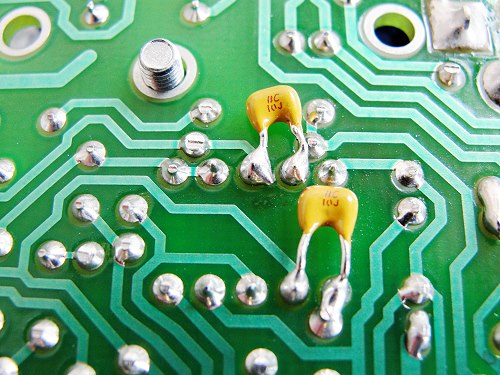 The ceramic 10pF capacitors are soldered between pins 1 and 2, and between pins 6 and 7 of the op-amp as shown. They need to be this size to fit in the gap between the PCB and the aluminium shield. These are Vishay multi-layer ceramics of the BC series. This is a skilled job and can burn your fingers if they're not made of asbestos! Careful not to break or overheat the capacitors, or the op-amp, or to short out any pins. A good brushing with some PCB flux solvent will help keep the board pollution free. 
Because the capacitors reduce the full power bandwidth of the amp to around 200kHz, the input slew rate needs lowering - the two upright resistors are usually 8.2kOhm - they need to be replaced by 18kOhm to bring the input filter below the amp's full power bandwidth. I can detect no difference in SQ. I'd like to include this mod in production but the very act of soldering these capacitors in takes the labour cost up. If the individual customer wants these fitting he/she can request them but at a few quid more for the extra work. If our DIY members try this dodge I'd be grateful if you'll publish your individual findings below. Graham ------------- That none should be able to park up and enjoy the view without a smartphone and the knowledge in how to use apps |
Replies:
Posted By: mrarroyo
Date Posted: 24 Apr 2010 at 1:44am
|
Graham, the Voyager is a portable amp and although I am not surprised some are using it as a home amp (it is that good) I wonder if the distortion is not caused by a using a weak battery or a DAC with a hotter than 2 V/rms output. ------------- Miguel |