Phono Preamp Project
Printed From: Graham Slee Hifi System Components
Category: DIY AUDIO
Forum Name: Free Audio Designs and Info
Forum Description: Graham shows his competitors how to design and gives you some great projects to build
URL: https://www.hifisystemcomponents.com/forum/forum_posts.asp?TID=745
Printed Date: 27 Mar 2026 at 1:59am
Software Version: Web Wiz Forums 12.01 - http://www.webwizforums.com
Topic: Phono Preamp Project
Posted By: Graham Slee
Subject: Phono Preamp Project
Date Posted: 25 Dec 2009 at 4:39pm
|
A PCB, case, and components kit will be offered at diy-audio-kits.com, plus we offer to build and test the Genera phono preamp project for all those not blessed with DIY skills - watch out for updates here. The "open-resource" Genera (generic) phono preamp project starts here. And the icing on the cake is my secret ingredient all constructors will be able to fit (for a modest cost) that turbo-charges this thing into a "tube" phono preamp, without any of the short-lived ghastly glass beasties!  This is a totally new project, and I've not tried it out in advance, so here you will also get an insight into what really goes into a Graham Slee phono preamp project. One thing we do have is the Gram Amp 2 Communicator phono preamp case printed with DAK (diy-audio-kits) logo and the name Genera. The constructor does not need it to build this project, but it will be offered along with a PCB to construct a neat phono preamp for those who want it. Here are the pictures of the phono preamp case. The technical bit starts next post.   ------------- That none should be able to park up and enjoy the view without a smartphone and the knowledge in how to use apps |
Replies:
Posted By: Graham Slee
Date Posted: 27 Dec 2009 at 7:33am
|
The Novo kit demonstrated that discrete circuitry could be very problematic to the inexperienced: too many things to get the wrong way round, and in the case of a transistor - the rest (or most of them) blow with it. Therefore, for the Genera phono preamp it has to be an op-amp (operational amplifier chip), and just one at that!. But is that a dual op-amp, or a single? In the Genera phono preamp it's going to be two singles, one per channel. The reason why will become apparent as the design progresses. What performance can you expect? I'm looking for another winner here, so this is not going to be second-fiddle to a Gram Amp 2 phono preamp: I want it to do better or at least equal. So how do I go about chosing an op-amp? First we have to take a look at the RIAA reproduction curve.  The chart [1] above shows the output from a RIAA record according to a magnetic (moving magnet or moving coil) cartridge. To end up with a flat frequency response, the phono preamp frequency response has to be the inverse - the chart upside down.  The above chart [2] shows the curve from the first chart, upside down - the black curve. It is part of the blue-grey curve which shows the extended frequency response we can expect. This is the RIAA reproduction curve of our proposed phono preamp. The red curve is the gain bandwidth product of an op-amp called the LF356, and below [3] is the same taken from the http://cache.national.com/ds/LF/LF356.pdf - data sheet : the curve has the callout LF156, which is the family name covering the LF356.  The gain is inside the curve, that is to say to the left and below the curve. At approx. 5MHz the curve intersects 0dB on the x axis. Therefore the Gain Bandwidth Product is 5MHz. In actuality it is stated on the data sheet as 4.5MHz. Where the gain is maximum at about 105dB - a gain of approx. 178,000, the bandwidth read from the graph is only about 30Hz. In fact, if we know the Gain Bandwidth Product is 4.5MHz then at 105dB gain the bandwidth is 4,500,000/178,000 = 25Hz, which correlates with our estimations off the graph. To ensure an undistorted phono preamp using this op-amp, the phono preamp gain and bandwidth needs to be well within the op-amps curve - a rule of thumb being a factor of ten. For a 41dB gain (just over 100, and suitable for a moving magnet pick up) as shown in the second [2] graph, the rule of thumb exists frequency wise. In the direction of gain we have over 40dB spare, which more than covers the rule of thumb... 40dB being 100. ------------- That none should be able to park up and enjoy the view without a smartphone and the knowledge in how to use apps |
Posted By: Graham Slee
Date Posted: 27 Dec 2009 at 11:36am
|
One frequently asked question is... Can the gain of a phono preamp be increased? My stock reply is NO. But then it's challenged: "but other manufacturers do so" Let's look at increasing this design's gain to 60dB - a factor of 10 - (at the 1kHz reference) on the graph below...  We now only have a factor of 4 in the direction of frequency, where we wanted the rule-of-thumb ten. There is still sufficient gain at low frequencies however. By getting too close to the op-amps Gain Bandwidth Product (GBW) curve we lose the accuracy of the reproduction curve - you may be able to see it is slightly different - and so the RIAA EQ component values need recalculating to give the required reproduction curve. Therefore a simple gain adjust or switch won't do! This is why so many universal phono preamps disappoint in one setting or another. Another problem is that being so close to the op-amp GBW curve is that we lose some stability, which can be seen by the steeper high frequency end of the 60dB gain curve. These are very important considerations when designing a proper high fidelity phono preamp. Edit: To get the gain required for moving coil from a single op-amp, a type with a transconductance (non-degenerated bipolar transistor) input stage is required to get the gain up (and also for low noise). It also requires a large GBW product. There are precious few op-amps that can do this. Therefore, at a later stage I shall discuss and provide a neater solution for moving coil. ------------- That none should be able to park up and enjoy the view without a smartphone and the knowledge in how to use apps |
Posted By: tg [RIP]
Date Posted: 28 Dec 2009 at 10:56pm
Following this with interest. 
|
Posted By: Graham Slee
Date Posted: 30 Dec 2009 at 12:03am
 Here's the internals of the LF356. What's striking is the virtual absence of PNP transistors! As engineers who've used their ears with transistor amps will tell you: PNPs are cr*p! Unfortunately many in Hi-Fi believe the opposite. Now, I know I don't have the writing skills of JLH - I don't have that convincing "it's like this because I say so". But the textbooks bear me out, and so does Analog Devices, although they use them in most of their op-amps, explaining that theirs are superior. However, I have always been left wanting - missing the sound I easily recall from my early days. Like I mentioned earlier: "I want this to be a winner". Where PNPs would be (in the differential input) there are P-channel FETs which not only perform better than PNP bipolar transistors (but not NPNs!), but don't suffer the poor linearity of a bipolar transconductance stage... By transconductance I mean bipolar transistors that don't use emitter resistors. Bipolars that use emitter resistors (as those in the voltage amp differential: R2 and R3) sound far better because they're very much more linear, but suffer noise because the emitter resistors degenerate gain, so there's less in the form of negative feedback, to reduce the noise. The LF356 FETs are no different - the noise stacks up alongside an equivalent degenerated bipolar input stage. But, if it were bipolars it would have to be PNPs to complement the NPNs in the next stage. So FETs here were a good choice! It also makes the LF356 have extremely high input resistance (impedance when talking about signals). I've used the very similar LF351 (LF353 dual) and the TLO71 (TLO72 dual, TLO74 quad) in phono stages, and they did sound really nice. The TLO71 variety was the only one to project Hendrix a good 4 foot behind the listening position (spooky), but in these days of noise specmanship... need I say more? Eagle eyed op-amp historians will also notice the NE5534 output stage!!! Transistor Q2 is an emitter follower driving Q14 which takes care of the negative going "push" and Q3 which takes care of the positive going "pull". Give Q14 some more current gain with an (erm) good PNP, and you have the same circuit as many a great old time high fidelity power amp! Designs such as that of Leak, as well as my 70's home built disco amp used such an output configuration, and progress has done little to better it. Notice C2 in the voltage amp differential. I'll be talking about that next. ------------- That none should be able to park up and enjoy the view without a smartphone and the knowledge in how to use apps |
Posted By: Graham Slee
Date Posted: 03 Jan 2010 at 4:39am
|
SLEW RATE From previous post: "Notice C2 in the voltage amp differential. I'll be talking about that next." Notice C2 is the same as C in the diagram below...  http://books.google.com/books?id=bkOMDgwFA28C&pg=PA407&lpg=PA407&dq=art+of+electronics+slew+rate&source=bl&ots=F2ehTL9YXv&sig=ZpxZikM6OPUiUf0dPkjqKF75clw&hl=en&ei=nx1AS-LaKJq60gSE26ySBQ&sa=X&oi=book_result&ct=result&resnum=1&ved=0CAgQ6AEwAA#v=onepage&q=&f=false - The above diagram taken from the Art of Electronics, Horowitz and Hill, as featured on Google Books (skip back a page) Here (fig. A) we have the innards of the opamp represented by bipolar transistors, but you may be able to see the similarities (because they are there) between it and the innards of the LF356 shown last post. Slew rate is one of those really hard to grasp properties in electronics. Here I will do my best to explain so you all understand it a bit better. Capacitors store charge. To obtain the charge you'd place a capacitor across a voltage. That would cause a current to flow from the voltage source for a period of time required for the capacitor to adopt that charge - with me so far? So we have five properties here: charge (Q) in coulombs; capacitance (C) in farads; voltage (V) in volts (of course); current (I) in amps; and time (T) in seconds. Now here is a (dreaded maths again!) formula... CV = IT (which means: C x V = I x T ) which is a great way for simple folk like me to remember what I'm supposed to be doing... Also, Q (charge) = CV, so because CV = IT, also Q (charge) = IT (yes?) Slew rate is volts per micro-second, and so we can use the V and the T like this: V/T (Voltage divided by Time), which represents volts per time (got it?). So we want to know V/T, and by rearranging CV=IT we get... V/T = I/C So volts per time = current per capacitance Great! From the data sheet we know the slew rate is 12V per micro-second which can be put as... 12/0.000,001.T (which means 0.000,001 x T, which means micro-second), or put it all on the top line (by doing dv/dt), which is 12,000,000. From the data sheet we know C = 10pf. 10pf is 0.000,000,000,01 Farads - a bit cumbersome, but never mind (the scientific among us will be making use of that calculator "x10x" key) So we now have, 12,000,000 = I/C = I/0.000,0000,000,01 So by rearranging the formula so that I is on the left (I = dv/dt x C) the current required to charge the capacitor that quickly is I = 12,000,000 x 0.000,000,000,01 = 0.00012 A = 120uA (120 micro-amps) which suggests that the current called Ie in the above diagram is 120uA, or that the current flowing in the differential input stage of the LF356 is 120uA ??? Not having the "confidential" information from National Semiconductor to confirm this, I can only assume that it is the case from what the maths say. But is 120uA is quite typical for this sort of J-fet input configuration? I would have thought it would be more, especially as the input noise voltage is pretty good, and that usually suggests more FET drain current than 120uA (60uA per device). And if the current were higher, then the slew rate would be higher too. But it isn't. The limiting factor here is input stage linearity. It's far better than that of a non-emitter degenerated bipolar transistor, but nothing electronic is perfect. But a transconductance input stage results in a slew rate 0.3 x bandwidth, which for 5MHz would only be 1.5V/uS. The LF356 is stated as 12V/uS which can be taken to mean that it is 12/1.5 = 8 times better linearity. So now you know where slew rate comes from, and how it can be related to bandwidth to reveal an op-amp's linearity, we can now proceed to design the RIAA filter (next) ------------- That none should be able to park up and enjoy the view without a smartphone and the knowledge in how to use apps |
Posted By: ServerBaboon
Date Posted: 03 Jan 2010 at 5:38pm
|
Head Hurts Spent some time looking for my old copy of 'Art of...' sure I still had it, your not getting any replies yet but from the views there is a lot of interest so please keep up. |
Posted By: Graham Slee
Date Posted: 03 Jan 2010 at 7:38pm
|
Get the paracetamol out! Here comes the RIAA bit! Here is a simplified active RIAA filter courtesy of one of the best guys in the industry: Walt Jung, from an Audio Engineering Society pre-print.  Now guess what we're going to discuss first? Yes, slew rate! (What? Again?) We need to know if the slew rate is sufficient for this RIAA phono preamp, and how the op-amp slew rate affects the choice of the RIAA replay filter component values. Just look at what's hanging off the op-amp output! A large value of capacitance in series with a small value of resistance (C1 in series with C2, and R3 in series with that). The op-amp has to drive that at 12V per micro-second. If it cannot drive it, it will become unstable and ring, if not oscillate. We could over compensate the op-amp, but that would be a waste. To answer if and what the LF356 output can drive we need a formula... And here again it's Q = CV = IT The first answer we need is to know if 12V/uS is sufficient, and a derivation of the formula gives SR (slew rate dv/dt) = 2pi x V(peak) x (1/T) (derived from from "Audio/Radio Handbook", National Semiconductor, 1980) We need to know the maximum output voltage (V), the desired frequency response to derive time (T), and later, the op-amp's output current (I), to find what capacitance it can drive. Now, the datasheet tells us it can drive some real heavy capacitive loads, but it won't be performing all that well while doing that: we want the op-amp to be lightly loaded to give off its best. So, we now need to gather the terms V, T and I. Voltage "V" is going to depend on a couple of considerations: 1] the power supply voltage, and 2] more importantly, how much the LF356 can take without its input leaving its linear (or near linear region). This will, in turn, determine the overload margin or headroom. When an input leaves its input linear region it still works, and it'll probably measure quite well on THD (total harmonic distortion), but on the inside it is under undesirable stresses if quality audio is what we're after. We found from the previous post, that the LF356 is 8 times more linear than a transconductance input op-amp. The maximum (peak) linear input for a transconductance input is about 50mV (before things get forced), so here it's going to be 50 x 8 = 400mV. That should be more than plenty, but hold on! The RIAA curve tells us that the output of a magnetic cartridge rises with frequency - how high? Musical instrument's fundamental frequencies don't go as high as you'd imagine, say 8kHz (often much less with traditional instruments). But perhaps the early harmonics have good output, so let's allow 20kHz. At that frequency the cartridge output is ten times higher than it is at 1kHz. Taking a healthy output of 5mV, used on a "hot pressing" (because the young are into vinyl too...), its output is going to be the same as a 10mV output cartridge (ref 1kHz), and so the input should be able to handle 100mV. Now that's RMS, so peak will be 140mV, which means we have headroom of nearly 3 (our 400mV divided by 140mV). Studio PPM meters redline at +8dB which is about 2.5. So on most high energy peaks this input will not distort as badly as a transconductance input (this is pereceived distortion, not steady state THD as based on a sine wave). That covers the high frequency requirements. Now, the rest (the lower frequencies which are lower output from the magnetic cartridge) are going to depend on what the preamp output can swing. Some hi-fi magazines state maximum input as being where the output of the phono preamp hits 1% THD. To determine what the output can swing before clipping (hitting the supply rail), we need to set out the gain we're looking for and determine the supply voltage... What about gain? I don't think it reasonable to expect a high performance phono preamp to directly drive a power amp. I'd be happy if it did a gain of 100 (40dB) which would give an output of 500mV for a 5mV sensitivity moving magnet cartridge. What is going to be the largest signal the phono cartridge is going to output? Consider something few others consider - the test tracks on a HFS75 test record (or similar) used to optimise cartridge set-up. Band C tracking test is +18dB and 18dB is times 8. So with a 5mV output cartridge its (normalized) output is going to be 40mV giving rise to a 4 volt output - can we accomodate that with a voltage supply suitable for the novice DIY enthusiast? One of the highest and easiest to obtain power supply voltages is the CPC 24 volt plug top "wall-wart", which also suggests this design needs to be single supply (and why not keep things simple?). However, that 24 volt is not regulated, so we need to choose a regulator that can do a slightly lower voltage, say 18V. On an 18 volt supply the maximum peak to peak swing is 18V if the op-amp can output rail to rail. Most cannot, and can only get within +/- 1.5 volts of the rail. So the maximum peak to peak is 15V. We are interested in the RMS voltage which is 10/28th of the peak to peak output, or 5.35V. So with a gain of 100, the maximum input is going to be around 53mV. That's +14.5dB for a 5mV cartridge playing a "hot pressing" and +20.5dB for the same cartridge playing band C of HFS75's worst tracking test.... good enough? So, as far as voltage is concerned, it's 5.35V RMS (7.5V peak). Time 1/T is frequency in the case of the first question we need to answer. It's the highest frequency we want to reproduce accurately. Often, in the past, designers simply plicked 20kHz out of the air, but is 20kHz really the highest frequency we want to reproduce accurately? Often, older phono preamps emphasised clicks and pops - well that was my earliest experience of phono preamps. Read about clicks and pops and you'll find that vinyl clicks and pops are all in the audible range. True, because they can be heard, so I guess that's how they justify that, but what about the leading edge of a scratch? Could a scratch be chissel shaped? I reckon so. It will have steep sides. So if we imagine the stylus is moving across the record (that's an easy one - for years man thought the Sun revolved around the Earth) at speed, then it finds it has taken off across this ravine, and then hits the cliff on the other side - ouch! It is not trying to reproduce the full width of the scratch, but the "cliff-edge" it just hit. That could be just ten percent of the width? So will 20kHz cover that? I don't think so. Maybe 200kHz? So let's see if 200kHz will fit our 12V/uS slew rate... Is the slew rate sufficient? From SR (slew rate dv/dt) = 2pi x V(peak) x (1/T) SR should equal or be higher than 2pi x 7.5V x 200kHz... is it? The answer is 9,424,777.961 V/S which is 9.4 V/uS, so 12 V/uS is sufficient! Can 12V/uS drive the RIAA filter? Here we need the op-amp's output current (I). When we find that we can use this derivation C = IT/V or I x 1/(SR x 1,000,000) (as you can see, this is derived from Q = CV = IT) to find what capacitance the op-amp will drive. So let's take a look at the http://www.national.com/ds/LF/LF155.pdf - data sheet (pdf) And guess what? It doesn't say! Often, output current is not specified in op-amp data sheets, so how are we going to find it out? One way is to look at the output voltage swing which is usually referenced to a particular resistive load. Here two loads are shown: 10 kOhms and 2 kOhms. Into 10 k it swings +/-13V and into 2 k it swings +/-12V. By the looks of it, 2 kOhms seems to be the limit (or corner) where its output swing starts to drop with increasing load (maximum power theorem), so I think we can assume that Ohms law will tell us its output current. I = V/R 12V/2,000 Ohms gives 6mA. Huh! That's where the output stage similarity with the NE5534 (which will do 16mA) ends! But still, the LF356 has got all the other features desirable for a phono preamp, so let's carry on. So by dividing 6mA by the inverse of and normalized slew rate we will see just what capacitance its output can drive whilst maintaining both stability and slew rate. from C = IT/V we get 0.006 x 1/12,000,000 = 0.000,000,000,5 Farads or 500pF! Now, luckily, that 500pF is the smaller of the two capacitors required (C2 in the above diagram) - the one that dominates at higher frequencies. But will 500pF (470pF being the nearest "prefered" or available value) result in unusable values for the rest of the filter? The only way to find out is to try it! This is where phono preamp design starts to become an empirical excercise. I'm going to finish this posting here to allow a page break (hopefully), and continue it in the next reply. ------------- That none should be able to park up and enjoy the view without a smartphone and the knowledge in how to use apps |
Posted By: Graham Slee
Date Posted: 04 Jan 2010 at 10:11pm
|
Looking at Walt Jung's diagram again... We see the dominant capacitor C2 is 10nF (0.01uF), and we worked out, that by not compromising the LF356 slew rate, C2 needed to be 500pF. What if we traded a little compromise which could mean having to over-compensate (or the op-amp's capacitive load drive compensating for us) such that slew rate is halved? 6V/uS is only 60% of what we said we'd need to go as high as 200kHz (to accomodate record surface damage)? If we could make C2, in the case of the LF356, 1nF (1/10th of the Jung value), we could simply scale the component values shown and we should get the required RIAA replay curve. The Walt Jung diagram results in 40dB gain (ref 1kHz), which is the gain we want. It would mean R3 being 1kOhm, and that will contribute extra noise, but maybe not that much to resort to a complicated solution, or scrapping the use of the LF356 altogether. The LF356 has so many good points, it would be a shame to have to drop it. At this point we could build a trial circuit and measure it, or simulate it. Simulations never tell the full story - a real circuit can be measured - but it may save us time by picking out unforeseen problems. I think at this point it would be a good idea to simulate and discuss the results. Stay tuned! PS. page break didn't work... ------------- That none should be able to park up and enjoy the view without a smartphone and the knowledge in how to use apps |
Posted By: Fatmangolf
Date Posted: 05 Jan 2010 at 12:30am
|
This is fascinating, thank you very much for sharing your knowledge on this project.
------------- Jon Open mind and ears whilst owning GSP Genera, Accession M, Accession MC, Elevator EXP, Solo ULDE, Proprius amps, Cusat50 cables, Lautus digital cable, Spatia cables and links, and a Majestic DAC. |
Posted By: Graham Slee
Date Posted: 05 Jan 2010 at 6:11pm
|
A PCB,
case, and components kit will be offered at diy-audio-kits.com, plus we
offer to build and test the Genera for all those not blessed with DIY
skills - watch out for updates here. Here is the schematic for the "sanity-check" simulation...  C test is where the capacitive load went. The phase margin with a 500pF load is...  ...(where gain cuts through 0dB) 180-120 = 60 degrees, which will not lead to excessive ringing. The gain margin with a 500pF load is...  ... around 25dB, so just better than our rule of thumb ten. The phase margin with a 2,200pF (2.2nF) load is...  ...180-145 = 35 degrees which indicates execessive ringing, but we may be able to compensate for this in a real design. The gain margin with a 2,200pF (2.2nF) load is...  ... around 15dB which is less than the rule of thumb ten (20dB = 10) ------------- That none should be able to park up and enjoy the view without a smartphone and the knowledge in how to use apps |
Posted By: Graham Slee
Date Posted: 06 Jan 2010 at 6:25am
|
By now most should realise phono preamp design is a bit complicated... Do you think there are lots of op-amps well suited to phono preamp use? Here, we have found one of the best in the LF356, but even then it's not perfect or easy to implement. Ever wondered why there are so few? Is it a fact that vinyl almost became extinct in the eighties? What suitable op-amps existed prior to then? I have seen one since and many rave about it. In fact there are 2 or 3, but they are in fact one and the same, just variations of the same design (one works on +/-18V, another +/-22V). In fact, they are 3, 4, or 5, because there are single and dual types. What should have "clicked" by now is that even with a high slew rate, which is condusive to good audio, without the current, high slew rate is useless. It is little wonder then, that these modern op-amps, although everything sounds different, lead to the eventual subjective conclusion (once the hype has worn off), that there has to be better. Therefore, although it could look like the LF356 is not the best choice, it has the input linearity needed, and it has a trick up its sleeve that the masses do not see - two additional inputs - and that may just clinch it. For the time being, we have to deal with the value of dominant RIAA filter capacitor, such that the Genera phono preamp sounds fast - gives a realistic tempo - and relegates vinyl surface noise to last place. We could simulate this design for the next 20 pages, but I'm sure that will bore the pants off everybody. So I'll launch straight into the wrinkles that will make this a viable design... We see that with a 2.2nF dominant capacitor we have little phase margin, but place a small value resistor in series with that, and it takes the impedance up to beyond the zero dB crossing point, and therefore provides more phase margin. This begs the question of what is the best phase margin? One thing for certain is that you can't get a full 180 degrees (which ensures absolute stability) because the op-amp (and it's the same for discrete including valves) is rolling-off - it can go no further - high frequency bandwidth is not infinite. As we have seen, all op-amps or amplifiers in general (when designed properly), when open loop - before the application of negative feedback to reduce the gain to what is required - roll-off from some frequency, and that rate is (or should be) 6dB per octave. That correlates to a phase angle of 90 degrees, which means there is 90 degrees left, and that's the phase margin. By assuming that using a 2.2nF dominant capacitor, that R3 (in the Jung circuit) is going to be scaled by the same factor, we arrive at 454 Ohms. The nearest prefered value is 470 Ohms. As this is a non-inverting amp, and we make the 2.2nF series resistor the same value, we see we have 6dB gain (x 2) at that frequency and all the way to where the output goes through zero dB. Therefore the phase will be near to 90 degrees (simulation suggest 94 degrees), and so it's going to be highly stable. But what about gain margin? Is that going to be our rule of thumb ten (-20dB)? No, it stays the same. How can the gain margin be improved? This is done by inserting some resistance between the op-amp output before the negative feedback take-off point. Coincidentally, the value here that takes gain margin to just better than 20dB is 470 Ohms also. But this has taken the bandwidth down to just 2MHz. It has slightly improved the phase margin to around 100 degrees. The reduced bandwidth of 2MHz means it will not slew as fast. From our earlier (important) exercise where we found the constant of 8 to go into the slew-rate formula (SR = 0.3mft) we can work out that slew rate is going to be about 5V/uS. This is just over half of what we wanted. In our earlier discussions we thought about using 1nF for the dominant capacitor, but then I explained that meant R3 being 1k, and its contribution to noise could be a "bridge too far". So here we're trading noise with bandwidth... Those of you who have followed the development of Graham Slee Projects Ltd, will have read me going on about trading bandwidth for noise, and the above proves the case! No, it wasn't just some slick advertising glob, I've been talking about reality all the time! While at this juncture, I am sure therefore, questions may be forming about our ultra-fast Era Gold V? How was that so fast? It could only do what it did by choice of op-amp and the 50KHz cutter head knee (using a similar series resistor in the dominant capacitor leg), which also served to improve phase margin. The value of its equivalent R3 was also larger than the low noise Jung example we are working from here... again it traded noise for bandwidth. But the slew rate of the Era Gold V could obviously not be the same as that of the op-amp, loaded by the RIAA filter, as it is - the op-amp's slew rate being 250V/uS! The filter did reduce it down, and the op-amp itself has a slew rate limiting network in its output stage, otherwise it would have been unstable. Also, as I have said above, without output current, slew rate is meaningless - the Era Gold op-amp does 50mA! nearly ten times the LF356. So why aren't we using it here? That's because of the number of "infant mortals", the Era Gold V op-amps failed noise-wise at the rate of 33%. You probably won't have the noise testing facilities we have, and therefore, even with good hearing, would, in all probability, not be able to tell. The LF356 is in a different class regarding noise failures, such that you have a 99.9% chance of having two perfect units in this design. So, with just over half the slew rate we deduced we needed in a utopian world (even so, it will handle "full-sensitivity" stimuli up to 100kHz well), I think we have here a high performance phono preamp in-waiting. At 5V/uS, it is far faster than the 60's and 70's designs (that still exist today in audiophile disguise) which were lucky to reach 1V/uS. Next we need to establish the rest of the RIAA filter component values, and then evaluate a few other considerations before arriving at a schematic to try out. ------------- That none should be able to park up and enjoy the view without a smartphone and the knowledge in how to use apps |
Posted By: iamalexis
Date Posted: 10 Jan 2010 at 11:58am
it is very interesting to be given an insight into the design side of things. i didn't realize quite how much is involved in the process. thanks for sharing this information/knowledge with the forum 
|
Posted By: RobW
Date Posted: 10 Jan 2010 at 10:36pm
Am trying hard to keep up but at every turn I find myself having to check my compass. Is there a good primer out there for the basics? I'm a mechanical engineer and have this annoying habit of trying to look at this subject through that filter ... electronics seems a bit like alchemy. Advice appreciated - I'm a late blooming enthusiast. 
|
Posted By: Graham Slee
Date Posted: 10 Jan 2010 at 11:05pm
The Art Of Electronics by Horowitz and Hill, Cambridge publishers, although expensive (mine cost 60 GBP about 15 years ago) should help greatly. The best place to start is right at the beginning of the book where you will discover the authors taking an intuitive approach. I too started out in mechanical engineering but moved into electronics at a gradual pace. Edit: At one point in my career my head of department (there were just two designers: he and me) was actually an industrial chemist... during that time we designed quite a lot for the BBC world service... so you stand a good chance ------------- That none should be able to park up and enjoy the view without a smartphone and the knowledge in how to use apps |
 RobW wrote:
Posted By: Graham Slee
Date Posted: 11 Jan 2010 at 10:42am
|
Thinking about what I just said above, this sort of thing can be tackled in the Audio Projects Magazine! After several months of reading text books on transistors in my youth, the real breakthrough for me came by reading one of the 1970's Everyday Electronics magazine teach-ins. I reckon a six issue course (bi-monthlies) on understanding electronics (or electronics made easy) PLUS at least one really useful audio project in each issue, must be worth 60 GBP on the year? Especially considering The Art of Electronics costs the same! (well, it used to) We could start with the fundamentals of Ohms law and work upwards - and have fun learning!  ------------- That none should be able to park up and enjoy the view without a smartphone and the knowledge in how to use apps |
Posted By: RobW
Date Posted: 11 Jan 2010 at 7:11pm
|
I reckon a six issue course (bi-monthlies) on understanding electronics (or electronics made easy) PLUS at least one really useful audio project in each issue, must be worth 60 GBP on the year? Especially considering The Art of Electronics costs the same! (well, it used to) We could start with the fundamentals of Ohms law and work upwards [/QUOTE] ___________________________ Hmmm ... are you considering spearheading this or suggesting I look for something?I already read the introduction to The Art of Electronics (on-line) and am interested enough to have reserved the book at the local University library. Can we spawn a new thread on this subject? |
Posted By: Graham Slee
Date Posted: 11 Jan 2010 at 8:45pm
|
Please feel free to do so
------------- That none should be able to park up and enjoy the view without a smartphone and the knowledge in how to use apps |
Posted By: RobW
Date Posted: 12 Jan 2010 at 6:22am
New topic spawned in DIY Audio Questions and Answers. A Route to Learning the Art? |
Posted By: Graham Slee
Date Posted: 12 Jan 2010 at 8:24pm
Now for the bit you've all been waiting for....................... Not quite a working schematic yet, but the bones of one.  The chart shows the RIAA response it results in (green curve), the phase response (red curve), and the input (blue curve). The input is applied across the 47k resistor and is then filtered by the 1.5k resistor and 220pf capacitor, and the blue curve is the result. Now, for a moving magnet input the blue curve is purely academic as its inductance dominates and the 1.5k isn't really "seen", therefore its load is simply 47k in parallel with 220pf. The curve will fall off far sooner than the 400kHz -3dB point (approx.). The reason for the 1.5k resistor becomes apparent when you consider its use with a high output moving coil cartridge which has much - much lower inductance and equivalent series resistance. The curve needs to fall earlier than the response of the amp stage - the input slew-rate can't be faster than the output slew-rate or distortion would be the result. In fact, it's a good idea to try and hit 1/10th the output slew rate which just about guarantees avoidance of this type of slew induced distortion. As you can see, I inserted a 3k resistor in series with the 2.2nf cap. Initially I reckoned on 470 Ohms, but slew-rate is Volts per Time, so we needed more gain at high frequencies to get that rule of thumb 10, or nearly 10, in the voltage domain as well as bandwidth domain. What it does however, is curtail the RIAA fall-off around 25kHz, and to be faithfull to the RIAA reproduction curve, we have to turn it back down such that it keeps falling at roughly 6dB per octave (20dB per decade). This is handled by the output filter (820R and 4.7nf). The response curve is within 0.3dB of the required RIAA curve using the common values shown - the 6.6nf cap being 3 x 2.2nf caps in parallel. Apart from the 3k and the 36k, all resistors are found in the E12 value series, meaning the constructor has a choice of carbon film or metal film resistors. In the case of the 3k and 36k resistors, these would have to be metal film to obtain the required value. In real life (so far we're in simulation land) this circuit may need some tweaking and that's why we have the required test gear. At least we have the starting values to be able to do a prototype. At this point what I now need do is grab hold of one of our old surplus Era Gold or Reflex boards which have most of the pads this design requires and build a trial circuit. The eagle-eyed will have spotted the improvement in gain margin (bottom-right of plot) to 30dB, which is down to the 3k resistor (it doesn't always work like this for all op-amps). More to follow - stay tuned. Edit: You may also have noticed the 4MHz 0dB crossing? If slew rate = 0.3 x m x Ft, and the constant "m" we found is 8, then 0.3 x 8 x 4(MHz) = 9.6V/uS, which, if my memory serves me well, is what we said we wanted. Good old 3k resistor! ------------- That none should be able to park up and enjoy the view without a smartphone and the knowledge in how to use apps |
Posted By: Graham Slee
Date Posted: 13 Jan 2010 at 9:44am
A PCB,
case, and components kit will be offered at diy-audio-kits.com, plus we
offer to build and test the Genera for all those not blessed with DIY
skills - watch out for updates here. So here we have it, our values built on a surplus earlier version of the Gram Amp 2 SE PCB, complete with reject back panel, and it will go into a reject SE case. There's quite a few other components that aren't on our schematic above: these I worked out as I went along, and I'll be showing you how, but this is just to get the bones of the design together so I can test it. As this board was designed for a dual op-amp, I'm going to need an adaptor board to mount the two LF356 single op-amps. Here I will use the little adaptor board I designed for the Elevator EXP and the Gram Amp 3 Fanfare. It's a bit like the "brown-dog" adaptor I've seen on "hot modding" forums. But seeing this board is pinned-out for a dual op-amp, I thought it would be fun to try a TLO72 op-amp. This is an op-amp I remember sounded particularly good in this kind of application (as mentioned before in this topic), and so we may well end up with a generic design where we can start out "simple" and mod upwards as we go. So, off I go back to the simulator to see the results of using a TLO72. Stay tuned... ------------- That none should be able to park up and enjoy the view without a smartphone and the knowledge in how to use apps |
Posted By: Graham Slee
Date Posted: 13 Jan 2010 at 2:41pm
|
A PCB,
case, and components kit will be offered at diy-audio-kits.com, plus we
offer to build and test the Genera for all those not blessed with DIY
skills - watch out for updates here. The simulation results for the TL072... Gain margin: 24dB Phase margin: 77 degrees 0dB Bandwidth: 1.8MHz Slew rate: 8.4V/uS (based on 0.3mFt) So it will work in the same circuit and should give similar results! But, I just thought, I have that horrible suspicion that we used up all the TL072's in some Elevator EXP's ages ago as servo op-amps... oh dear! So what else could I use? I'm pretty sure I have a LF353, which is a dual version of the LF351, and this gives these results... Gain margin: 19dB (borderline maybe?) Phase margin: 78 degrees 0dB Bandwidth: 2.25MHz Slew rate: 7.5V/uS (based on 0.3mFt) Still quite close, and thinking about it, both should be because they share broadly similar chip topographies. I think what we should therefore do is offer the option of dual or two single op-amps! Such a small case as the Genera's which, like I said, is just a Gram Amp 2 Communicator case printed differently, may not easily take two completely separate channels, so why not stick to a simple initial implementation that's easy to build for the novice, then offer the adaptation to LF356 for later on? Seems like a great idea for the novice, and provides the phono preamp "hot modders" a go at upgrading knowing that they're not in unchartered waters - the differences are going to be there, but not because of any instabilities. It also gives me the opportunity of redesigning the Communicator PCB at the same time - in fact it will be the same PCB! The Communicator may use different op-amp technology (bipolar op-amp) but the "bones" are the same, just that the values differ. So now I'm off to place a DIL socket on the prototype and make up an adaptor board so I can try at least 2 of the 3 options above, and you never know, all three if I can find a TL072. I will photograph what I make and do test measurements to accompany them, then I'll give them an initial listen and give you my impressions next reply. I'm just a bit cautious that the LF353 and TL072 could be a bit noisier based on the data, but we'll find what the real measurements say. ------------- That none should be able to park up and enjoy the view without a smartphone and the knowledge in how to use apps |
Posted By: Graham Slee
Date Posted: 14 Jan 2010 at 1:17am
|
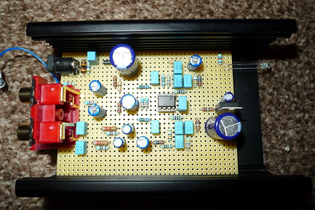
Couldn't find a TL072, and the LF353 had seen better times - one channel very noisy, but I did find an enhanced TL082, which is in turn an improved TL072 - an AD712. No internal schematic exists in the data sheet, but the spec gives it away as being very similar apart from having 4 times the output current. Simulating it showed it very close to the TL072 whose results are in brackets... Gain margin: 20dB (24dB) Phase margin: 73 degrees (77 degrees) 0dB Bandwidth: forgot to note it down (1.8MHz) Slew rate: 13V/uS (8.4V/uS) (based on 0.3mFt) So it fulfilled the need for a dual op-amp to try. Therefore we now have three choices of dual op-amp so it's happy chip rolling all the way... So here's some measurements - firstly the op-amps (as part of this particular circuit) LF353 Noise: -65dB CCIR Q-Pk 20Hz - 20kHz; -77dB A-wtd. Distortion THD+N: better than 0.04% ref 1kHz (mix of odd and even harmonics) Clipping: +16dB for 18V single supply AD712 Noise: -69dB CCIR Q-Pk 20Hz - 20kHz; A-wtd. not measured. Distortion THD+N: better than 0.035% ref 1kHz (mix of odd and even harmonics) Clipping: +16dB for 18V single supply TL072 No sample available. LF356 (single requiring adaptor board) Noise: -72dB CCIR Q-Pk 20Hz - 20kHz; -80dB A-wtd. Distortion THD+N: better than 0.04% ref 1kHz (mainly even harmonics: 2kHz) Clipping: +16dB for 18V single supply Here's a pic of the LF356 in the prototype phono preamp using the adaptor board...  and one of the AD712 in the prototype phono preamp...  Measuring the RIAA response showed errors in the simple scaling of the Jung schematic, from which were derived the starting values earlier. The 36k resistor was changed to 33k (E12 series, enabling the choice of carbon film, which is what I used) because the 10kHz frequency read -14.3dB instead of the desired -13.7dB. The resulting reading was -13.8dB one channel, -13.9dB the other. The 100Hz gain was too high, therefore the 6.6nf value (3 x 2.2nf in parallel - a third one was soldered under the board for those looking at the earlier photo) was altered to 6.9nf by paralleling a 4.7nf with a 2.2nf. This made a little difference but not enough, so the 470k resistor was changed to 390k, which gave +13.2dB one channel, +13.3dB the other - close enough to the required +13.1dB at 100Hz. Because of the above changes, the gain had dropped to 38.75dB, so changing the 470R to "deck" to 390R made it 40.25dB - close enough to our target 40dB (ref 1kHz). Here are the RIAA measurements common to all the op-amp implementations, and the deviation (in brackets) from the RIAA reproduction curve... 20Hz: +18.8dB/+18.8dB (-0.5dB/-0.5dB) 100Hz: +13.2dB/+13.3dB (+0.1dB/+0.2dB) 315Hz: +5.3dB/+5.3dB (+0.1dB/+0.1dB) 1kHz: 0dB/0dB (reference) 3150Hz: -5.2dB/-5.4dB (-0.2dB/-0.4dB) 10kHz: -13.8dB/-13.9dB (-0.1dB/-0.2dB) 20kHz: -19.3dB/-19.5dB (+0.3dB/+0.1dB) Therefore the maximum deviation is "end to end" at 0.8dB, but between 100Hz and 10kHz it's 0.4dB. Put another way, you're going to be hard pressed to hear it. The RIAA spec allows 2dB. The above is using 5% tolerance components, apart from the 3k resistor which is 1%. Do we really need precision components? I don't think so. So, next up will be the schematic of the complete phono preamp with a quick discussion on the other components not yet shown. Then we need a PCB. ------------- That none should be able to park up and enjoy the view without a smartphone and the knowledge in how to use apps |
Posted By: discrete badger
Date Posted: 14 Jan 2010 at 8:36pm
|
What a fascinating insight this is turning into, Graham. Anyone with ears can hear the results in your products, but to learn about how this comes from methodical and logical design decisions is really a privilege. De-mystifying the process just makes it all the more impressive! Thank you! |
Posted By: Graham Slee
Date Posted: 15 Jan 2010 at 5:52am
|
A PCB,
case, and components kit will be offered at diy-audio-kits.com, plus we
offer to build and test the Genera for all those not blessed with DIY
skills - watch out for updates here. Erratum: Pin out for IC1 dual (TL072/LF353) inverting and non-inverting pins reversed on 1st op-amp - should read: non-inverting + 3 (5); inverting - 2(6)  Here we see the completed schematic of the prototype Genera phono preamp. So far, this design has been built on a "donor" PCB, and still requires a PCB of its own, and therefore, having not been finally prototyped and tested, the above schematic may, or may not, contain unforeseen complications. Having said that, it doesn't look like it. It can be seen that some components are suffixed "A", and some are not. Those that are not are common to both channels. The rest (suffixed "A") refer to the left channel - for right channel components (not shown for clarity purposes) these would be suffixed "B". Looking at the common components: these are the power supply jack J3 to junction R13, R14; the bias reference supply R11, R12, C9; the op-amp decoupling capacitor C10; and if the op-amp is a dual device, IC1 (if not, then IC1A). The power may be derived from any 24 Volt DC (positive) supply with the caveat that if a 25 Volt C13 is used, this must be a regulated supply. If an unregulated 24 volt DC supply is used, then because of the light load presented by the circuit, its voltage will rise as high as 36 Volts, and therefore C13 must be rated more highly than 36V. L1 is a small inductor which in conjunction with R15, C14 and C13 the other side of diode D1, effectively attenuates power supply "nasties" such as high frequency noise. D1 is included to protect the unit from accidental inverted polarity connection to the supply, and is after the high frequency capacitor C14, otherwise it could rectify incoming radio frequencies. Because of the Kirchoff or Kelvin return current from the output, some signal will flow in C13, and therefore this should be a good quality electrolytic capacitor - a good general purpose unit will suffice. A supply is taken off via R16 for a light emitting diode (LED D2) panel lamp. A fixed +18V IC voltage regulator IC2, provides local "on-card" voltage regulation. R14 is a small value resistor which prevents parasitic oscillation of the voltage regulator. C11 improves the regulators transient response at all audio frequencies in this design. R13 is included to prevent power supply spikes from interactions with the parallel film capacitor C10 (op-amp decoupling capacitor), during high energy - high frequency signal excursions. As this phono preamp is single supply, it must derive its "0 volts" reference from a voltage splitter. Because it is single supply it is not really 0 volts, but half the supply voltage to allow its output to swing symmetrically. R11 and R12 serve this function, but being connected directly to the supply, do not offer any power supply rejection to the op-amp input. C9 is included for that purpose. Its value is such that it will provide "stiff-opposition" to any feedback via the supply back to the input, at all pass frequencies, especially the bass where the gain is highest. This voltage splitter effectively prevents "motor-boating", a low frequency oscillation effect. That covers the common to both channels components - I'll be back right after this break... I'm sure some will be horrified by the use of three electrolytic capacitors in the signal path, C1, C6 and C7. The main objection to using electrolytics in the signal path is that they distort badly, and this is true where there is no polarising voltage, but here there is, it is inherent with all single supply designs. Another objection is their poor dilectric absorption rate, and again this is true for low voltage electrolytic capacitors, therefore use a higher voltage (hint: you will find the "sweet spot" in the 63V - 160V region - remember valves? the ones that used HT!). Why such a large value in the input? Here you need understand how an op-amp "sees" its input (its source) as a "noise control" (yes, even J-fet inputs). As source impedance rises so does noise. If we used a small capacitor (470nF would easily cover the entire audio range) the source impedance would be "seen" to be rising with decreasing frequency. Noise is always worse at low frequencies (and maximum gain here is also at low frequencies - a "double whammy"), therefore the source impedance needs to be kept low at low frequencies and with a 1k Ohm DC resistance moving magnet cartridge via a 470n input capacitor, the source impedance rises to 33k Ohms at 10Hz - 33 times its DC resistance. Another reason for such a high value (100 uF) is to match the one on the other input (C6). Making both inputs the same - capacitive as well as resistive - should allow the output to adopt its mid point immediately on switch-on: or put another way, the output of an op-amp will do whatever is necessary to make both its inputs the same. We want it to do 9 volts (half rail) so by us making both inputs the same for it, it should go straight to 9 volts. In actual fact it does not. We must remind ourselves that we're using a J-fet op-amp (high impedance inputs), and therefore initial capacitor leakage comes into play. A bipolar input op-amp requires lots more input bias current, absorbing most of the initial leakage current of the two electrolytics C1 and C6. Therefore, this design will not do instant switch-on - it takes quite a few seconds. We may well find that by reducing the value of C1, we get faster switch on, but the lowest we dare go is 10uF or input noise will start to become a problem. We cannot reduce the value of C6 or we will attenuate the low frequencies. C6 sets the low frequency "roll-off" (-3dB) frequency which is 4Hz for 100uF. Now, at 10 times that frequency there should be a 1dB reduction in output where the phase is almost flat again (-12 degrees in actuallity), therefore at 40Hz our RIAA filter should be 1dB down, but it isn't. Specmanship is always more important in Hi-Fi... I'm guilty of pandering to the aloof here, I admit to cheating the "curve" to make the "spec rhyme", but I will offer corrective remedies for the true purists. Often, I have seen elaborate solutions at getting rid of the negative feedback ground coupling capacitor (in our case C6), but these only work in a dual rail supply application, and that's where there is no polarising voltage (hence the reason for getting rid of it). The main solution used is a "servo" more correctly known as a slow-integrator. The "servo" is required or there would be a massive DC output offset. Without going into a lengthy description on how "servos" "crowbar" down the offset, I will simply say, that by intuition, their complexity is such that they can influence performance. Therefore, I think, by careful choice of a good general purpose capacitor (see my voltage hint above) there will be very little difference in performance between the "servo" controlled solution and this one. As for the output capacitor C7, my voltage hint applies here too. I have also chosen the value of R9 to "improve" C7's performance. R9 also serves to quickly charge C7, and to minimise "clicks" when "hot" connecting the phono preamp output to an input, or when switching between inputs on some "non-muting" preamps. Another break... Input impedance It has been many years since vinyl "ruled the roost" and so it is forgiveable that many do not understand input impedance. The input impedance here is made up of two resistors in parallel, R1 and R2 producing just over 47k Ohms. There is also another parallel resistance, that of the op-amp input, but being FET (field effect transistor) it will be so high as to be of little consequence. Some will not see how R2 could be in parallel with R1, but at AC frequencies (from a fraction of a Hertz) capacitors C1 and C9 make it so. C1 couples the signal end of R1 to the signal end of R2, and C9 couples the other end of R2 to ground (GND, 0V). This phono preamp is suitable for moving magnet cartridges, moving iron cartridges and a type of moving coil cartridge that has a high output. Anything from 2 to 10mV (ref 1kHz) will work. The cartridge spec may tell you the cartridge resistance, and with the above range of cartridges that can be from a few Ohms to a couple of thousand Ohms. They will all work into 47k Ohms. There is also a capacitive input impedance. Here it is 220pF (pico-farads). It will only have a barely audible effect on one type of cartridge - the moving magnet one. It's influence on moving iron and moving coil only comes into play very high up in frequency. The reason for R3 is to ensure these cartridges do not peak, or produce a spiked response, when influenced by the sharp edge of a scratch. If not for R3 then the spike produced (a fast pulse) would drive the phono preamp into severe clipping - out of control, the phono preamp would "ring" for a longer period than the sharp edge of a scratch, so long in fact, that it would be heard as a loud click. There will be surface noise, you cannot remove it without removing music too, but R3 serves to minimise its effect. With a moving magnet cartridge, because of its rising AC resistance versus frequency, due to its high inductance, R3 is so small as to have no consequence, and C2 is "seen" as being in parallel with R1||R2. People are convinced that minor adjustments of the value of C2 will lead to a big improvement in sound quality. They are very misled. The frequencies of concern are 13kHz and above, and the difference in amplitude is around 1 - 3 dB. Such differences are hard to hear at normal audio frequencies, never mind at 13kHz or above. However, people do hear a difference and I believe them and can explain what that difference is, and it is nothing to do with golden-hearing. It is the difference you will always get between switching out an "in-use" capacitor to a "cold" capacitor - that's all. And that's why you hear so many contradictory opinions of what capacitance or other suits a particular cartridge. In fact, if you make the capacitor 500pf or even 1000pf, it WILL make an audible difference, and if at the same time you make the input resistor (the value of our two paralleled resistors R1||R2) 68k or even 100k, it will lead to an even bigger difference. Some claim this to be better! These people would prefer tone controls because that's what they are in-effect applying, but suggest such a move and you will be held in contempt... For moving magnet, the 47k input impedance must also always be accompanied by a capacitance for moving magnet to deliver its flatest response, and that capacitance is going to be between 200 and 300 pico-farads depending on whose standards you choose to work to. DIN or IEC says 300pf. The 300pf is made up of approx. 80pf arm cable capacitance (measure a Technics arm and cable capacitance for evidence) and a 220pf input loading capacitor, and you can see this design uses the DIN or IEC standard. The reason is because a tuned circuit is needed to extend the drooping response of such a high inductance that moving magnet cartridges represent. Let's do the math.... from F (frequency) = 1/2pi sqrt LC (sorry, cannot show math symbols here), with L = 500mH (average for a MM cartridge) and C = 300pf, we get... 1/ 2pi x sqrt (0.5 x 000,000,000,3) = 12994.94669Hz or 13kHz. Change for 200pf 1/2pi x sqrt (0.5 x 000,000,000,2) = 15915.49421 Hz or 16kHz If it were not for this tuned "LC" (or tank) circuit the frequency response would already have taken a hike. With 300pf the frequency response is pulled up about 2-3dB at 13kHz and then starts to fall. With 200pf the frequency response is pulled up about 1 - 1.5dB at 16kHz and then starts to fall even faster. The averaged result is "flat" to about 18kHz and -12dB (second order filter) beyond that, whichever solution is tried. The 47k resistor damps the "LC" tuned circuit to prevent it peaking too much. If you increase it above 47k the peak becomes larger and the roll-off goes to a higher frequency, and if you decrease it below 47k, the peak becomes lower or non-existent that it rolls off much lower in frequency. Phono preamp designers can sometimes use different resistive input impedances to make up for shortcomings in their designs, then justify what they have done in such a way that everyone believes all phono preamps must be the same. The loudest shout gets the most attention. The "LC" tuned circuit has no similar effect on moving iron and high output moving coil cartridges because their inductance is much smaller - 47mH for a Cartridgeman Music Maker for instance. However, without the 1.5k resistor (R3) their response would be greater than the amp stage causing slew rate distortion (a high frequency effect similar to adjusting the wrong mixture on a carburetor causing "hunting", for the sake of our older engineers...). There would also be very high frequency peaking which would not be a problem, apart from the fact that records get scratched. Another break.... ------------- That none should be able to park up and enjoy the view without a smartphone and the knowledge in how to use apps |
Posted By: RobW
Date Posted: 16 Jan 2010 at 3:22am
Nice touch. I despise that little detail when it's overlooked. |
Posted By: Graham Slee
Date Posted: 18 Jan 2010 at 6:45pm
|
It's PCB time! This is how a PCB design starts in our office on my favoured ancient (1980's) DOS 5 compatible software. Much better to be able to see exactly what you're doing. New flat screen was just a twinkle in somebody's eye back then, so mine has to be a widescreen to get square squares and round circles...  ------------- That none should be able to park up and enjoy the view without a smartphone and the knowledge in how to use apps |
Posted By: mrarroyo
Date Posted: 18 Jan 2010 at 8:58pm
|
The more I read the less I understand. I must repeat that we are two countries separated by a common language. ------------- Miguel |
Posted By: Graham Slee
Date Posted: 18 Jan 2010 at 11:37pm
Yes, this is true, and please inform president Obama that we received Winston Churchill's statue back in good condition after spending near on 60 years in the Whitehouse.... But when it comes to electronics, Silicon Valley and NASA speaks the same language, just that I try to make it more layman. The problem with any tiny company like ours showing the world how to design, is that I have to be exact and methodical or some individuals who think they run companies to similar standards, may just be able to trip me up. I suppose I could just say that it sounds out-of-this-world or mind-blowingly-good, which incidentally it does, but I'd be stealing everybody else's line...  ------------- That none should be able to park up and enjoy the view without a smartphone and the knowledge in how to use apps |
Posted By: Graham Slee
Date Posted: 19 Jan 2010 at 2:08am
So far so good... The left hand screen is the design copied into the windows software because I cannot get a hardware compatible MS DOS 5 printer these days. Even with the disadvantage of having to do transfers on floppy disc, the "machine-code" version of this software is mega-fast compared. Time for checking, final tweaking, then generating the gerber and drill files before emailing to the PCB manufacturer for some prototype PCBs. ------------- That none should be able to park up and enjoy the view without a smartphone and the knowledge in how to use apps |
Posted By: discrete badger
Date Posted: 19 Jan 2010 at 7:21am
|
Graham, when drawing out the board like that, how much are you thinking about the sound quality effects of your decisions versus the more obvious task of getting everything to just fit onto the board and be connected in the right way? |
Posted By: leo
Date Posted: 19 Jan 2010 at 5:00pm
looking great, its giving me itchy fingers would love a go at this, may even knock it up on vero (if Graham don't mind) until the kit is released, better have a trip to Craplins to see what bits they don't have would love a go at this, may even knock it up on vero (if Graham don't mind) until the kit is released, better have a trip to Craplins to see what bits they don't have Its nice to see a diy phono stage, don't seem to be many of these about, anybody else having a bash? |
Posted By: Graham Slee
Date Posted: 20 Jan 2010 at 6:09am
Like the Avatar! "Twas twillig and the slithy tove..." Graham don't mind! Looking forward to your findings - hope craplins has some veroboard - wish I had some left too! ------------- That none should be able to park up and enjoy the view without a smartphone and the knowledge in how to use apps |
Posted By: Graham Slee
Date Posted: 20 Jan 2010 at 6:56am
Good question! Did you know that when you are listening to music you are actually listening to the power supply?  Here is how... (Transistor Man picture from "Art of...": points B and E is the input signal and points C and E are in-effect the amp controlling the power into the speakers, headphones, a preamp driving a power amp etc)  We will assume the power supply is nice and quiet with enough current to prevent it "wobbling" in sympathy with the music. What else could go wrong? Even with short and reasonably thick PCB traces, a "dot to dot" will have sufficient impedance for one thing drawing power to affect another thing drawing power (like the headlights dimming when you switch on the rear window demister, or that recurrent "MOT-pass because they don't test them together" Ford earth fault which turns the rear indicators off when the brake lights come on). And the thing many designers forget: currents flowing into and out of the same point at the same time - it can't be done - that point cancels out completely when the currents are the same and in direct opposition - a case of a piece of wire that is solid, it is there, you can see it, you can even "bleep it out", but it's not connected! Therefore, you may be able to make out a number of tracks all going to the same place by different traces? That place is the lowest impedance point of whatever current we are wanting to connect to. Often the star earth is the only thing considered, and often the star earth is just a "pretty flower picture" with a silly thin track then leading back to the common "ground" connection - so all those currents still modulate one another (search the internet if you want a good laugh). In our case the PCB is routed to avoid one thing modulating another. We may only be talking about pico-amp differences, but those are sufficient to confuse the picture as the all-important "clues" are contained in the micro-information. Some designers adopt the ground-plane approach, but the current still takes its own path as if the rest of the ground plane didn't exist. So yes, I'm thinking most of the time about sound quality effects of my decisions, and often miss a connection because of it  . So right now I'm correcting things like that, doing print-outs, checking again etc. . So right now I'm correcting things like that, doing print-outs, checking again etc.------------- That none should be able to park up and enjoy the view without a smartphone and the knowledge in how to use apps |
Posted By: RobW
Date Posted: 20 Jan 2010 at 8:07am
Hey - I was just reading about "Transistor Man" on the weekend. Thanks for the tie in.

I very much like the thought-shift provoked by the idea that listening to music is basically listening to the power supply. So is the source signal then just the mechanism that controls a "rheostat" between the power supply and the transducer? And all the other bits and pieces in the signal path are just about ... what ... balancing, filtering, controlling ... ? I need to look over your schematic closely to see if I can see what you're talking about re PCB routing to avoid modulation. So many questions. |
Posted By: leo
Date Posted: 25 Jan 2010 at 10:16pm
|
I've been wanting a bash at a diy phono stage for ages so this to me was hard to resist
Most of the bits including the black Hamond aluminum case came from Maplin, the vero board was actually the cheapo stuff without the copper strips so the circuitry was point to point wired on the bottom, all grounds was star earthed using instrument cable which now cover most of the board.
The Evox film caps come in packs of 5 from RS, the other bits like the Panny caps from Farnell, I wanted to keep the component choice as close to Grahams as possible including the LF353 op-amp (also from Maplin) only thing which is different I used was the resistors, Maplin don't seem to stock carbons so I used metal films because they are sold in singles , they only come in packs of 50's or whatever from Farnell and RS.
Its actually surprising how much things add up if your sourcing everything yourself so a full kit would certainly be great
I'm currently running it in using a plug in linear PSU , I won't comment too much yet on the sound as things tend to change a lot during burn in, as most already know capacitors go through the forming process but initial impressions are very good
Turntable I'm using is the Technics SL-1210 MkII
A big thanks to Graham for sharing this project, I think its nice a guy selling top phono stages goes to the trouble of sharing this with the diyers, also being active on a thread during the design makes it special imo
Anyway I'll be buying the kit once its available , it'll look far better than my knock up version
 |
Posted By: mrarroyo
Date Posted: 25 Jan 2010 at 11:51pm
|
Nice work there Leo, I have not used a turntable in over 15 years but you never know. However I will not attempt to build one if I got back in, instead I would buy an already built unit. To many fires! ------------- Miguel |
Posted By: leo
Date Posted: 26 Jan 2010 at 12:08am
|
Thanks Miguel,
I'm actually quite new to vinyl, I'm just starting to get a small collection , I was brought up with cd
BTW we all get burned fingers from time to time
|
Posted By: tg [RIP]
Date Posted: 27 Jan 2010 at 7:34am
|
Seeing Leos prototype almost has me itching to have a go myself. Not as if I need another phono stage, but we just can't keep from fiddling can we As Leo says, rather special to have been fully informed during the design decision making process. Many thanks to Graham for that, it has been a most informative ride. |
Posted By: Graham Slee
Date Posted: 28 Jan 2010 at 12:40am
It isn't over yet ------------- That none should be able to park up and enjoy the view without a smartphone and the knowledge in how to use apps |
Posted By: Graham Slee
Date Posted: 29 Jan 2010 at 2:20am
Genera built! Tested and working, and looks like the PCB is OK. ------------- That none should be able to park up and enjoy the view without a smartphone and the knowledge in how to use apps |
Posted By: iamalexis
Date Posted: 29 Jan 2010 at 10:59pm
| Nice work! When might this be available? Also will you be offering various options, including the "turbo charging" upgrade you mention at the beginning of this article and elsewhere on the forum? |
Posted By: jonclancy
Date Posted: 03 Feb 2010 at 11:21pm
|
Wow! Awesome stuff, Graham! Thanks for the design insight. How does it sound, Leo? |
Posted By: mrarroyo
Date Posted: 03 Feb 2010 at 11:45pm
|
Nice work there Graham, would you mind sumarizing the intended use of this phono stage? That is, is it for MM, MC, etc. BTW, what PSU should it be paired with? Thanks. ------------- Miguel |
Posted By: Graham Slee
Date Posted: 04 Feb 2010 at 12:46am
Working on a kit right now. The board performs well and I now need to get some component stock sorted as well as a nice little construction manual and the packaging. The "turbo-charged" op-amp "piggy back" board is also in the process of final tweaking. This is the "ultra-linear" application I've been referring to. It should be simply a matter of plug and play, replacing the dual op-amp - I'm hoping constructors can tell the difference. For other various options see the next reply down... ------------- That none should be able to park up and enjoy the view without a smartphone and the knowledge in how to use apps |
Posted By: Graham Slee
Date Posted: 04 Feb 2010 at 1:04am
As the Genera is generic, starting off as a basic but good performance phono preamp, we should be able to make it do the works with moving coil too. But for the time being this is a "working man's" phono preamp: in its present guise it's a moving magnet sensitivity "workhorse" which should be equally at home in the vinyl fronted domestic hi-fi system, as well as in its other intended use as a DJ phono preamp where it should really wow the crowd... Let's call it a high output cartridge phono preamp, because it's not just for moving magnet but high output moving coil also. With a gain of 100 (AV = 100, or 40dB) a 2.5mV high output moving coil will cause it to have sufficient output for most integrated amps (250mV). With a 5mV output moving magnet it will do 500mV, and for the DJ playing "hot" pressings from 12 inch 33 rpm singles the output will be nearer a volt. I am running the prototype with one of those little "green" switchmode supplies, but I'm sure a difference would be heard with a "good and solid" linear supply design. That's something worth looking into next, but in the meantime I wouldn't mind recommending the PSU1 ------------- That none should be able to park up and enjoy the view without a smartphone and the knowledge in how to use apps |
Posted By: RobW
Date Posted: 04 Feb 2010 at 6:03am
|
My wife can already see the writing on the wall ... the inevitable entry point back into vinyl after my 15 year hiatus. Warm up the check book honey.
|
Posted By: leo
Date Posted: 04 Feb 2010 at 9:31am
It sounds very sweet and has improved after some running in, sound is more focused and tighter in the bass than it was when I first fired it up.
I've tried various recordings and it handled them all well
One of these would be ideal for a mate of mine ,when the kits are available no doubt I'll have to build it for him though
Leo
|
Posted By: jonclancy
Date Posted: 04 Feb 2010 at 10:06am
|
Sounds very promising, Leo. The immediate competitor that springs to mine is the CA 640P. Seeing at that the 640P has such a huge following around the Bazaars, a configurable and tweakable DAK offering has the potential to become very popular indeed. And now that the vinyl renaissance is underway... What strikes me is that there are a million and one people out there who will never hear about this project, but who might be looking for this exact thing. As Graham said, DJs for starters. But what about all those at Lenco Heaven, PFM, Vinyl Engine, DIYA, WAD, AOS etc etc who want a good performing, but reasonable cost phono amp? Protocol says you can't crosspost to push a product, but, like the DIY Magazine idea, I think exposure beyond the (growing) audience here would help. Anyway, I'm looking at this with interest. I have my workroom finally tidied, an finishing off the latest RG board prototypes (which incidentally will be a bolt-on extra for this project) and then I'd like to finally get round to reviving one of the old TTs I have in storage here! Cheers Jon |
Posted By: iamalexis
Date Posted: 04 Feb 2010 at 6:09pm
so it won't be too long to wait...i have a friend just getting back into vinyl and i'm hoping to build this for him
|
Posted By: Sylvain
Date Posted: 20 Feb 2010 at 10:12am
|
Graham
Any news on the Kit launch.....dribbling as I read and re read and look at all the work you have put in and is it ready to bring to market ....can't wait soldering Iron already hot and silver loaded solder .......
Sylvain
|
Posted By: Graham Slee
Date Posted: 22 Feb 2010 at 7:40pm
|
Doing the write-up... Taking a bit of time. G ------------- That none should be able to park up and enjoy the view without a smartphone and the knowledge in how to use apps |
Posted By: Graham Slee
Date Posted: 30 Apr 2010 at 3:54pm
|
Testing is something we attach great importance to. One of my mentors told me not to rush headlong into launching a product until you've tested it, tested it again using another batch of components, and better tested it using yet another batch of components... another who is not an electronics engineer but an electrical engineer, relayed the words of a wise joiner... measure twice - cut once! It is therefore wise to also test the build-ability of a project... This is not a kit. This is a project! It's done in the spirit of the old magazines that helped hone my "art". This is "Practical Wireless", "Everyday Electronics" and "ETI" in one. It is supposed to inform rather than shout. The results are your own work - the work of your hands with guidance from some pages I wrote. The instructions are in the form of a "magazine" article. This is not painting by numbers. This time it assumes the builder has the desire to learn. The "pre-printed" article is shown very much as I expect it will appear in a few days time to others. What's missing below the printed circuit overlay in the last column is a photo from those below - the one showing the completed board. This post is supplementary, intended to be the "painting by numbers" bit not included in the project - I never saw a project in a magazine having to go into such great detail - I never heard of a magazine holding the constructors hand - the constructor made his (her) own version to his (her) best abilities.  This is my workbench, and on it the opened blister-pack of PCB assembly parts, and to the side of it the "pre-print" article it comes with (there is also a case, case hardware, and a switched mode power supply like what goes with products like the "Fanfare" which you can read about on this owners forum... it works)  Taking it logically I started at the top of the component list and assembled the first resistor values on the PCB.  Rather than a photo of each resistor value going in, this shows the board with all resistors soldered on.  I included this one because it shows the op-amp socket the right way up - you can still see the orientation print on the board at the top.  For the taller components I inverted the board onto this foam pad which forms to their shapes - holding them in provided you exert a little downward pressure on the PCB as you solder. Even so, the components can "rock over" - skills are required but that's why the human race has a thumb where it is!!!  Here I have selected components of similar size to assemble each "layer"  When it comes to the little electrolytics, rather than forcing them right down to the board, spraining the wires apart that may allow the bung to leak, it is best to stop before you reach that... this is how the wires emerge the solder side of the board. The small electrolytics are nearly flush with the board but not quite which you might just be able to tell below.  Another layer of components done - some of the larger electrolytics and the voltage regulator.  Setting the op-amp in the turned pin socket: take it easy here to ensure the op-amp pins don't bend under or out. Ensure they're all centered before pushing home gently.  Don't forget this link or the left channel won't work! There is no tinned copper wire in the parts pack! I used the wire clipped after soldering in one of the electrolytic capacitors (the can shaped capacitors).  The phono socket is equipped with location tabs but there was no room for a slot to locate the tab nearest the DC power socket. Therefore it must be clipped flush as shown.  The completed board - this is the picture which will be included in the article.  Assembly of the case should be self explanatory from the pictures - above shows plug-in feet.  The TT ground post being assembled from the inside...  ...and from the outside...  ...completed.  The PCB mounting pillars are attached by the M3x6 screws with a serrated washer under each to make for case ground continuity.  Showing the mounted pillars - these are left slightly loose until the board is assembled into the case so that the PCB screws align - then all screws are tightened - DON'T FORGET!  The phono block is aligned and coaxed into the punchings and secured using the self tap screw from the hardware bag.  The board is screwed down to the pillars - this one makes with a track on the underside to ground the board to the case. Note that one of the serrated washers is used under each pillar screw.  The LED has to be formed through the hole... this shows the right way round. The LED gives a dull orange/red glow. The LED legs have to be cranked...  ...bent over and offered up to the punching...  Then the legs straightened to make it sit so that it is not easily pushed back into the case. I thought I'd do mine badly so that yours might be better...  The lid goes on easier if inverted as shown  The case is not a masterpiece in engineering - it is very basic. It is simply folded 1.5mm aluminium that has been anodised and aluprinted. You will find a gap exists between lid and chassis - if it didn't have a gap the anodised finish would get scratched forcing the two pieces together. If you try and adjust the bend of the case "on your head let it be" should the case be damaged - we will not be sending out any free replacements - you have been warned.  This is the one I built. I then tested it on our audio test set and measured... Gain: 40dB ( x 100 ) THD (distortion) measured at 1kHz: 0.02% RIAA accuracy: within 0.5dB at frequency extremes, 20Hz to 20kHz Crosstalk: -60dB Noise: PPM wideband (worst possible measurement) -64dB CCIR 20Hz - 20kHz (my usual technique) -66dB A weighted curve (what Hi-Fi manufacturers use) -75dB If built properly and you can only hear a bit of hiss, and you have connected the turntable properly "earth" wise, and everything sounds about right, you can assume yours will measure similarly if such equipment were available. ------------- That none should be able to park up and enjoy the view without a smartphone and the knowledge in how to use apps |
Posted By: Sylvain
Date Posted: 01 May 2010 at 5:14pm
|
Yes yes yes more more more . Have a good bank holiday and now we can see the light at the end of this long tunnel and it is looking good to me ..........testing my iron and 3% silver solder on the ready.. ''Genera is TRULY coming!!!!!!!!!!!!! |
Posted By: iamalexis
Date Posted: 02 May 2010 at 4:34pm
how does the genera perform with a linear power supply? is a psu1 kit, or similar, going to be available in a kit/electronics magazine format? nice work mr slee. myself, like sylvain, am ready and waiting
|
Posted By: Fatmangolf
Date Posted: 04 May 2010 at 6:40pm
|
I have placed my order as I promised and am actually quite excited about receiving my Genera kit. Watching Graham develop the design over the last few months has been very informative, on the basics it reminded me of reading HE, EE, and the other magazines. But it's on another level when a top designer builds the thing in front of you.
It will be worth the wait. I am really looking forward to the build and burn in, then the listening bit that will take much, much longer.
------------- Jon Open mind and ears whilst owning GSP Genera, Accession M, Accession MC, Elevator EXP, Solo ULDE, Proprius amps, Cusat50 cables, Lautus digital cable, Spatia cables and links, and a Majestic DAC. |
Posted By: Sylvain
Date Posted: 04 May 2010 at 8:45pm
|
|
Posted By: Graham Slee
Date Posted: 04 May 2010 at 9:04pm
|
Yes, some form of ultra-linear module will be offered to upgrade the Genera to valve like characteristics. For the time being I think constructors will like the results of the standard issue. The Kits Shop for UK members is now open! http://www.gspaudio-community.activeboards.net/forum_posts.asp?TID=880 - http://www.gspaudio-community.activeboards.net/forum_posts.asp?TID=880 ------------- That none should be able to park up and enjoy the view without a smartphone and the knowledge in how to use apps |
Posted By: Graham Slee
Date Posted: 05 May 2010 at 1:32am
Hi Jon, At the risk of repeating myself, it's been a long held ambition of mine to resurrect the interest in DIY electronics - especially in DIY audio - that there used to be via Hobby Electronics and "big sister" ETI, as well as Practical Wireless before it went purely Ham and CB, not forgetting Everyday Electronics (EE). My only previous experience in writing magazine type construction articles was my "one hit wonder": the Slide Tape Synchronizer in EE 30 years ago. In hindsight it was quite amateurish, but I was only in my early twenties, and it did make the cover shot... The problem in doing this today, plus having a reputation to hold onto, is that the attention to detail required is phenomenal! The Genera "pre-print" instructions is an article in its own right, written in "the style" some of us might remember, but doing all the "typesetting", photography, diagrams as well as getting the explanations right is very wearying and extremely time consuming. There must be a "formula" to all this, or maybe it needs the "mob-handed" approach? If it does, then it seems obvious why these publications ceased. 30 years ago I got paid £70 for the four page article - £560 in today's terms. Publications such as EE relied on contributors, but without sufficient incentive their contributions were bound to become lack luster repeats of "741 fuzz boxes", "555 egg timers" and "ZN414 AM photo-cube radios". So what killed the magazines? Was it the chicken or the egg? Did boring articles turn off the reader, or was it the lack of takers that led to the boring articles? The one saving grace I can identify is the spin-off of article related sales - component kits and the like... It is doubtful that the sales of a magazine alone could sustain attention grabbing construction articles, but the good old magazines would not do such a thing (apart from Elektor that is) because they didn't have the skills at their own finger tips. For a while Practical Wireless had some form of tie-up with "Readers Printed Circuit Board Services" of Whitwell, Notts - the owner of that firm and a friend just up the road often developing and writing the articles under various pen names (I knew the guys), but the bottom eventually fell out of that one. What with all the uncertainty in the world today - volcanoes disrupting all sorts of daily tasks, unprecedented oil slicks, grand fraud, unstable money markets, unstable nations, riots... perhaps there are too many distractions for such a project to be noticed?  ------------- That none should be able to park up and enjoy the view without a smartphone and the knowledge in how to use apps |
Posted By: Sylvain
Date Posted: 06 May 2010 at 8:08pm
| Paypal have acknowledged my Order, I have the NOVO' power supply and a 24 Volt power supply. Would have preferred a cost saving on the additional switch mode PSU and Postage for the Valvee characteristic module. Would have wished for choice of capacitors and resistors to achieve the type of sound to complement my type of accoustic folk and 60's -70's jazz . Can't wait to hear how my collection of LP's will now sound. bUT IT HAS BEEN A LONG WAIT AND MUCH LEARNED FROM GRAHAM SLEE design and development of the Genera Phono. |
Posted By: Fatmangolf
Date Posted: 06 May 2010 at 9:51pm
|
I read your reply to my post Graham and was thinking about the time you spent on the Genera design, the meticulous detail in the part ordering and kit packaging, and the excellent instructions. Thank you for all of this, it really shows and you have my utmost respect.
We've exchanged posts before on the magazine articles from the electronics hobby of the late '70's and early '80's. My apologies for making you repeat yourself about this. To be honest I thought my technical knowledge and experience were obsolete with the dominance of digital electronics, however I got back into building and modifying electronics when I decided to learn how the various valve amps modelled in my Line 6 Pod worked. Forums like this one are great for the hobbyist but I don't know how we get new people on board either.
It would be great if more people had a go at building or modifying electronics. It is a great way to learn and the discipline of making a reversible modification certainly helps. Even little things like experimenting with cartridge loading may help. (I am not asking you to repeat yourself here!)
Anyway the Genera kit is fairly easy to build, it was 90 minutes from opening the packaging to playing an LP. Obviously it works immediately, in fact it sounds alright them, but will improve as the components burn in. Build the Genera kit and learn how a simple design executed well can be very good indeed!
May I end by saying the good manners of everyone in the forum and Graham's expertise and ability to explain are the main reasons I have visited this owners forum regularly. We should be posting signposts to this forum so people know about the Genera project.
------------- Jon Open mind and ears whilst owning GSP Genera, Accession M, Accession MC, Elevator EXP, Solo ULDE, Proprius amps, Cusat50 cables, Lautus digital cable, Spatia cables and links, and a Majestic DAC. |
Posted By: Graham Slee
Date Posted: 07 May 2010 at 2:43am
|
Jaques, Thank you for your order - it is booked to ship out later today. The parts pack is a "bundle" where it is cheaper to "bundle" the whole thing together and package a whole batch rather than (Yorkshire expletive coming up...) fannying about individually packing things to the individual taste... We offer value for money as you very well know! If you think the cost of a wall-wart equates to the value of our ultra-linear module, well, I didn't want to say this because it sounds rude, but you must be out of your mind! You have spent many hours on the phone with us, sometimes venting your spleen at John, initially pressing us to sell you an SE in kit form when most people would realise that would take hours writing out all the assembly instructions... What you're getting is a simply housed phono stage parts pack on par with the SE, but when converted to use the ultra-linear module will be almost Reflex M quality... The Reflex is £418.94 (with the same power supply as we're bundling in the parts pack)! The Ultra-Linear module upgrade for the Genera will not cost the £308.94 price difference, but neither will it be for the price of a bundled wall wart - let's get real? Please comment after trying it. There are plenty of "leg lifters" who will (if you allowed them to) charge you £100 for a few bull-crap "quality" capacitors, and they know ****-all about audio. The ultra-linear module is ground breaking leading edge stuff! With all due respect to my Chinese customers I think some people have grown too used to the Chinese giving them an easy ride - quality for peanuts. They seem to have forgotten that "fellow Europeans" must also eat? (although I do try to get by on a bowl of rice...) Quote: "Would have wished for choice of capacitors and resistors to achieve the type of sound to complement my type of accoustic folk and 60's -70's jazz" So what capacitors would they be? I suppose that fitting the ones we fit in the top of the range stuff isn't good enough? Such as the French made polypropylene capacitors that wee- wee all over Wima's? They're in the parts pack! Maybe the French are no good? I would disagree. Tell me - if you put boutique caps in a heap of sh*t will it sound better than a properly designed stage that uses general purpose components? Some people think so you know??? However, I credit you with more intelligence than them. But I can tell you now that the Genera parts pack isn't stuffed with general purpose components - its packed full of the BEST components we've found in our very long experience - 36 years in my own case. And finally, please can we drop the word Valvee? My explanation was that the ultra-linear module replicated the wanted characteristics of a valve. ------------- That none should be able to park up and enjoy the view without a smartphone and the knowledge in how to use apps |
Posted By: Sylvain
Date Posted: 07 May 2010 at 10:05am
| Thank You...waiting for the UPS man. I did not imply a ''plug top24v dc '' exchange but know that your designs work well for me as I heard the GRAM.2 SE compared to many and totally sold. But know that i shall not be able to resist the ULTRA LINEAR MODULE with the claim characteristics of natural organic warmth as only Valves can thought that I do not need an extra power supply, and further post and packing charges to compound costs. Value adds to perception of good sound or the overall satisfaction when listening to LadyBLACKSMITH MAMBAZO on Vinyl or my full collection of Bob Marley 180 gms staright from ''TUFFGONG'' Vinyls press or Sarah VAUGHN very special delivery of ''You embraceable You'' or '' April in Paris'' or ''September Song'' on 180 gms vinyl or Quincy Jones arrangements of Sarah VAUGN on a special album. Satisfaction and added value will be for the DIY input and read that certain capacitors and resistors, Welwyn' apparnetly warmer than Wima's, Nichicon better than ... and so on, I read and even 'ground input output'' arrangements can accentuate the Mid to mid high frequencies whre '' my musical taste live much'' and it was the desire to add a little customising with your guidance that I was after. Anyhow, that eventually will achieve the remarkable output quality of the ''Reflex'' ADDS TO MY ENTHUSIASM. |
Posted By: Fatmangolf
Date Posted: 08 May 2010 at 10:21am
|
Sylvain, I hope you enjoy your Genera as much as I have and it does justice to your fine record collection.
To everyone who can build electronics I recommend the Genera kit highly. It is a straight forward build thanks to Graham's meticulous preparations for the kit. The article about circuit design is very clear and interesting. Best of all the preamp sounds quite good when first switched on and has just got better (clearer sound and great dynamics) each day since then. You get the best of the hobbyist electronic experience I remember, learning circuit theory and operation whilst building something that works very well.
Here are some photos of my completed Genera kit. [moderators are welcome to edit the list]
      Hope you enjoy this as much as I did, and still am! (Edited by Graham Slee to correct typo only) ------------- Jon Open mind and ears whilst owning GSP Genera, Accession M, Accession MC, Elevator EXP, Solo ULDE, Proprius amps, Cusat50 cables, Lautus digital cable, Spatia cables and links, and a Majestic DAC. |
Posted By: RobW
Date Posted: 08 May 2010 at 4:20pm
Hello Graham, when do you expect the kit to be available to the rest of the civilized world? 
|
Posted By: Graham Slee
Date Posted: 09 May 2010 at 3:19pm
Hi Rob, As soon as I clear this latest pile of paperwork I am off to PayPal's button creator to make the required links to paste into the European and Rest of World kit/parts shops. It could be today, tomorrow or soon to misquote Humphrey Bogart G ------------- That none should be able to park up and enjoy the view without a smartphone and the knowledge in how to use apps |
Posted By: Sylvain
Date Posted: 11 May 2010 at 9:23am
| UPS man delivered late yesterday Monday and I immediately took a little feel. It is small enough and since all advice has been to keep it near the Thorens TD 16OB, WILL FIRST INVESTIGATE what the arm wiring can do or whether a little shielded cable can do the trick. Read the accompanied literature but had seen the post so nothing new. Notice the remarks about '' by passing capacitors '' issues which may be a furture tweak and again all advice seem to indicate that indeed a significant rather than marginal sonic improvements can be achieved. Also the issue of RFI and wonder some ceramic capacitors by the input inductor may be useful. Finally, there has been much talk bout proper ground earthing assiting a clearer sound...need to understand the arrangement. OH Yes ideas in my mind as to hard wiring the input and output tag connectors to board, shortest length of pure silver wiring...but would it do much sonic difference. So this is the stage that the mind wonders and consider....the plan is to start populating the board by the week end. |
Posted By: Graham Slee
Date Posted: 11 May 2010 at 2:10pm
|
I'd build it first - listen to it for a couple of weeks - then decide
------------- That none should be able to park up and enjoy the view without a smartphone and the knowledge in how to use apps |
Posted By: Fatmangolf
Date Posted: 11 May 2010 at 7:11pm
|
Graham knows best!
I used silver solder and built the kit as supplied. Two days later I swapping the 220pF input caps for 100pF, realised Graham's comments on the input loading are spot on and put the 220pF caps back in. Then I started to use it instead of trying to modify it. It is remarkable just how great such a simple circuit can sound when it is expertly designed and has carefully chosen parts.
Great concept for a generic PCB/design and great kit. I probably will try the bypass caps next month and maybe make an adaptor board for 2 single op amps at some point. But at the moment I'm too busy enjoying the vinyl! ------------- Jon Open mind and ears whilst owning GSP Genera, Accession M, Accession MC, Elevator EXP, Solo ULDE, Proprius amps, Cusat50 cables, Lautus digital cable, Spatia cables and links, and a Majestic DAC. |
Posted By: Graham Slee
Date Posted: 12 May 2010 at 1:11am
|
Jon, the MC version will have a double op-amp adapter board, but don't ask me what I'm going to put on it ------------- That none should be able to park up and enjoy the view without a smartphone and the knowledge in how to use apps |
Posted By: Sylvain
Date Posted: 12 May 2010 at 11:00pm
|
Thank you thank you and good and appreciated advice.
But anything to harmonise the Goldring 1042 loading with the circuit. Anyone...please!
Any tweak resitor capacitance value changes. whilst I set to get building
|
Posted By: Graham Slee
Date Posted: 13 May 2010 at 1:01am
|
The 1042 has a slightly early electrical roll-off due to its higher than average inductance (570mH) but the stylus tuning may take it considerably higher. The standard Genera loading lets it peak by +1dB at 10kHz and then it's 3dB down at around 15kHz, which isn't far different to most MM's. Like I say, stylus tuning may well boost that so it's "flat" to 20kHz. I've heard it reported that the 1042 has a resonant peak around 2kHz of only 2dB so a 1dB peak at 10kHz could sway the "see-saw" in favour of the highs. The 1042 can sound a little too smooth (warm) so the standard Genera loading could be quite helpful here. Remember, we are only talking about 1 or 2 dB. If the 220pf load cap were to change to 100p the roll-off is more gradual (soft) and you may prefer that, but in a way, I wouldn't. It may be OK for classical but I reckon Bob Marley would be a lot better with the subtle extra snap of the standard load. G ------------- That none should be able to park up and enjoy the view without a smartphone and the knowledge in how to use apps |
Posted By: Fatmangolf
Date Posted: 13 May 2010 at 9:35pm
|
"Jon, the MC version will have a double op-amp adapter board, but don't ask me what I'm going to put on it
"Graham, we'll wait for it! I'm almost tempted to try a MC cartridge when that version of the Genera comes out. The MM version makes my modified P3-24 and Exact sound even better every day. Thank you again for sharing this project. Jon ------------- Jon Open mind and ears whilst owning GSP Genera, Accession M, Accession MC, Elevator EXP, Solo ULDE, Proprius amps, Cusat50 cables, Lautus digital cable, Spatia cables and links, and a Majestic DAC. |
Posted By: Fatmangolf
Date Posted: 06 Jun 2010 at 6:27pm
|
Hi Graham, 2 different questions where I (and others) would value your expert advice:
1) would you change the Genera's standard input loading for a Rega Exact cartridge?
2) what value(s) and spec of bypass capacitors would you recommend fitting to the Genera, please?
Best wishes
Jon ------------- Jon Open mind and ears whilst owning GSP Genera, Accession M, Accession MC, Elevator EXP, Solo ULDE, Proprius amps, Cusat50 cables, Lautus digital cable, Spatia cables and links, and a Majestic DAC. |
Posted By: Graham Slee
Date Posted: 06 Jun 2010 at 8:58pm
1] If anybody knows the spec of the "Exact" and can tell me, I may be able to comment, but it isn't even in Rega's information. All it says is "parallel wound coils". 2] I haven't even thought of it yet but a good stacked film polyester type such as http://docs-europe.origin.electrocomponents.com/webdocs/002a/0900766b8002a2e5.pdf - http://docs-europe.origin.electrocomponents.com/webdocs/002a/0900766b8002a2e5.pdf (it's a PDF), should work well. 10nF tends to do well and worth the experiment, but all bypass capacitors can cause an ultrasonic spike, which although being well beyond the audio spectrum, any stimulus (like a scratch) will cause the amp to clip - if it occurs (which it could) - and therefore you may hear some difference placing a 1 Ohm resistor in series with the bypass cap. Worth a try across C1A and B, C6A and B, and C9. Polypropylene can be better but I'd avoid Wima types in this design. I may offer the Evox types used in the EQ at some point but need to try them myself as values may differ from above. ------------- That none should be able to park up and enjoy the view without a smartphone and the knowledge in how to use apps |
Posted By: Fatmangolf
Date Posted: 07 Jun 2010 at 6:53pm
|
Thanks Graham, I think I will end up measuring the inductance on a used Elys 2, as it either shares the Exact design or is pretty similar. Rega's "parallel wound" could mean anything, it suggests a lower inductance but who knows!
On the bypass caps I have learned a lot from your answer so many thanks. If you would like to sell me 4 of those Evox caps, I will gladly make a contribution to your R&D fund! Jon
------------- Jon Open mind and ears whilst owning GSP Genera, Accession M, Accession MC, Elevator EXP, Solo ULDE, Proprius amps, Cusat50 cables, Lautus digital cable, Spatia cables and links, and a Majestic DAC. |
Posted By: Fatmangolf
Date Posted: 01 Jul 2010 at 9:37pm
|
Fellow members, has anyone else built Graham's Genera kit and how did it go? ------------- Jon Open mind and ears whilst owning GSP Genera, Accession M, Accession MC, Elevator EXP, Solo ULDE, Proprius amps, Cusat50 cables, Lautus digital cable, Spatia cables and links, and a Majestic DAC. |
Posted By: Sylvain
Date Posted: 02 Jul 2010 at 12:36pm
|
I have. Took a two stage approach. Populating board, admiring and resting for a few days.
Got a friend to assist with soldering and alligning in box. Fitted all components and tested to notice the beautyful dot glow on the fascia. Such relief. Now I used a British design Mosfet Amp fitted with a two stage Surface mount phono card module mounted vertically that is surrounded with much capacitor regulation and ceramics caps for emf cancellation. So connected the Genera via Line Amp phono. Tried som French ballads and eventually some Neil Diamond. The difference is more than just a new sound ..it is bolder on the ''Genera'' more solid. Vocals though not the best I have heard is much much better...I can live with the new sound and be happy for a ggod while. However, I now have thoughts of ''Cusat'' interconnect and have hinted to GSP to make these available as a KIt off the reel as I am very professionally coached on Phono plug soldering. Those ''by -passing'' capacitors also awaited as much as the ''ULTRA LINEAR '' module. Then, I shall connect to my 3OOB single ended but due to value and life of those mighty expensive valves, am constrained to use on very privilege occasion and certainly not for '' burning In '' the Genera. All in all I am happy, a good investment better than the Rotel Phono I praised in the late 80's and my aim is '' valvee warm and natural tone of vocals and timbre of instruments''. I believe the '' Genera'' is a good platform to achieve these objectives. HOWEVER, the eventual cost of updating the ''Genera'' with by-pass capacitors of the right sound, linear module hopefully will not deter me. There is value and a sense of dignity and pride in building your own with a master design of GSP calibre.
|
Posted By: Fatmangolf
Date Posted: 04 Jul 2010 at 12:03pm
|
Sylvain, thank you. I am enjoying my Genera kit for the very same reasons as you. And you are right about the importance of the interconnects.
Jon ------------- Jon Open mind and ears whilst owning GSP Genera, Accession M, Accession MC, Elevator EXP, Solo ULDE, Proprius amps, Cusat50 cables, Lautus digital cable, Spatia cables and links, and a Majestic DAC. |
Posted By: Fatmangolf
Date Posted: 04 Jul 2010 at 12:07pm
|
Graham, following an earlier posting on this topic I have now measured the impedance of an Elys 2 at various frequencies. It has Rdc 174 ohms and the inductance seems to be just over 100mH. So I would like your thoughts on the loading I could try with the Genera.
Best wishes Jon ------------- Jon Open mind and ears whilst owning GSP Genera, Accession M, Accession MC, Elevator EXP, Solo ULDE, Proprius amps, Cusat50 cables, Lautus digital cable, Spatia cables and links, and a Majestic DAC. |
Posted By: iamalexis
Date Posted: 08 Jul 2010 at 11:07am
|
i have been following this topic with interest as i received my kit a little while ago, but haven't found the time to build it yet. i'm looking forward to it, especially having built to novo kit last year with such good results.
i would also be interested to know if there are any plans to offer a diy interconnect. i'm also looking forward to the ultra linear mod to the genera, although i first need to build it and spend some time listening
|
Posted By: Sylvain
Date Posted: 09 Jul 2010 at 9:59pm
|
|
Posted By: Fatmangolf
Date Posted: 09 Jul 2010 at 10:45pm
|
I echo Sylvain's views on the Genera. My records have never sounded better than this. If there is an ultralinear upgrade that improves on the basic Genera I will be even happier. Thank you Graham.
PS what do you think about the 100mH and input loading? ------------- Jon Open mind and ears whilst owning GSP Genera, Accession M, Accession MC, Elevator EXP, Solo ULDE, Proprius amps, Cusat50 cables, Lautus digital cable, Spatia cables and links, and a Majestic DAC. |
Posted By: Sylvain
Date Posted: 10 Jul 2010 at 11:19pm
|
|
Posted By: Fatmangolf
Date Posted: 19 Jul 2010 at 9:53pm
|
Thanks Sylvain. Considering the electrical interaction of the 100mH inductance of the pickup coil and the Genera's 220pF loading in a Spice simulation, I found a peak of about 8dB at 27kHz. This ignores the mechanical stuff like the cantilever and the disk and the arm. Anyway Spice simulation suggests that lowering the resistor from 47K to say 18K would lower this peak to about 20KHz. I tried this and found little audible impact on dynamics, in my forties I probably couldn't hear the peaking frequencies in either electrical circuit.
Like you I found that the sound of my Rega Exact was very good with Graham's original 220pF and 47K in the Genera. I also have a Goldring 1012GX, not as good as your 1042 stylus but same coils etc. Similar sound quality with Genera's stock values. My view - Graham knows best on this.
------------- Jon Open mind and ears whilst owning GSP Genera, Accession M, Accession MC, Elevator EXP, Solo ULDE, Proprius amps, Cusat50 cables, Lautus digital cable, Spatia cables and links, and a Majestic DAC. |
Posted By: Fatmangolf
Date Posted: 19 Jul 2010 at 9:57pm
|
It's another great kit from DAK and very satisfying to build something this good. ------------- Jon Open mind and ears whilst owning GSP Genera, Accession M, Accession MC, Elevator EXP, Solo ULDE, Proprius amps, Cusat50 cables, Lautus digital cable, Spatia cables and links, and a Majestic DAC. |
Posted By: Sylvain
Date Posted: 22 Jul 2010 at 6:30pm
|
Agree...things are sounding better....and the fulfillment of casually hinting to people '' I built it...added a few tweaks...'' . Joan Armatrading nd her guitar though never a good fan of her vocals has returned on the Thorens 160B turntable. I seem even to wait to appreciate her music for the rendition of the Genera. Yes Just take it stage by stage and perhaps by Christmas we will be offering ourselves the ''icing on the cake ...the super linear module....with valve characteristics....to meet my HIFICOLLECTIVE 300B single ended amp.
Yes I have caught the D I Y bug but more comfortable than fishing by the lake.
|
Posted By: Fatmangolf
Date Posted: 24 Jul 2010 at 5:53pm
|
I am currently using my Goldring 1012GX which has a different stylus but the same magnet/coils/body as the 1042. I have tried changing the 220p and 47K load at the Genera input and Spice modelled the electrical circuit.
With the 1012 I concluded that the 220p is right but with a lower input resistor, about 33k sounded better. You can get 33k by putting a 100k across* each of the input phono plugs, leaving the 47k and 220p on the PCB. In Spice the change in the electrical circuit removed the 2dB peak at about 10KHz, leaving a smooth roll-off.
*shunted from signal to ground. You could hard wire the resistor across the plugs on the record arm's cables, rewire the PCB, even fit a decent dual potentiometer inside, or use phono T-adaptors like I did. This saves powering down the Genera.
Overall it is like turning the Treble down slightly, or a "tone" control as Graham Slee has pointed out. In my opinion the 1012GX is quite bright so I liked the impact of adding the 100k resistors.
The impact of these changes to the loading of the cartridge is very clear thanks to the Genera's excellent design and high quality parts.
------------- Jon Open mind and ears whilst owning GSP Genera, Accession M, Accession MC, Elevator EXP, Solo ULDE, Proprius amps, Cusat50 cables, Lautus digital cable, Spatia cables and links, and a Majestic DAC. |
Posted By: Graham Slee
Date Posted: 26 Jul 2010 at 4:57am
 The above schematic is included to aid this part of the discussion. The cartridge windings (coil) is L The capacitive load of the arm cable plus the 220p load cap in parallel is C The 47k input impedance is R Reducing R will damp the resonance (as per the above reply) - reduce the peaking. The actual output from the cartridge is this shape /\ The upward side is +6dB/octave, and the downward side is -6dB/octave. However, after RIAA replay equalisation the upward side becomes flat and therefore the downward side becomes -12dB/octave. Just thought this might help in understanding. ------------- That none should be able to park up and enjoy the view without a smartphone and the knowledge in how to use apps |
Posted By: Fatmangolf
Date Posted: 27 Jul 2010 at 8:55pm
This is the slightly more complicated electrical schematic I used: 
Add the cable and Genera capacitors together (320pF) to get C in Graham's schematic.
I tried shunt resistors of 10M (top curve with peak), 100K (middle curve - damped) and 47K to get the curves below.
 This circuit model is interesting and quite helpful but two things to keep in mind:
1) This is electrical only and ignores the cantilever and other physical parts of the cartridge.
2) Use your ears to make the choices on loading. (Like any of you need me to tell you this!)
Jon ------------- Jon Open mind and ears whilst owning GSP Genera, Accession M, Accession MC, Elevator EXP, Solo ULDE, Proprius amps, Cusat50 cables, Lautus digital cable, Spatia cables and links, and a Majestic DAC. |
Posted By: Graham Slee
Date Posted: 27 Jul 2010 at 9:10pm
|
Brilliant stuff!
------------- That none should be able to park up and enjoy the view without a smartphone and the knowledge in how to use apps |
Posted By: Fatmangolf
Date Posted: 27 Jul 2010 at 9:15pm
|
Thank you Graham, but it's your finely tuned hearing and design expertise we're here for! ------------- Jon Open mind and ears whilst owning GSP Genera, Accession M, Accession MC, Elevator EXP, Solo ULDE, Proprius amps, Cusat50 cables, Lautus digital cable, Spatia cables and links, and a Majestic DAC. |
Posted By: Sylvain
Date Posted: 05 Aug 2010 at 9:12pm
|
This is Good stuff and correct loading is better understood now. I can see why those charging £000,00 for their kit make such an issue for the correct loading with the cartridge /arm interface with the phono amp. I may be tempted to tweak at a later stage but for now things are fine....but my Vinyl collectin are very much 60'/70's accoustic guitars and male and female vocals and if the accoustic is reproduced with the natural veuve and Miriam Makeba with Belafonte' are as harmoniously and emotionally felt as reproduced on my Genera...then things are fine....no capacitor adjustment needed for now. |
Posted By: Fatmangolf
Date Posted: 08 Aug 2010 at 6:41pm
|
Glad to share Sylvain.
If you are interested I also ran a circuit model with 50pF added capacitance instead of the 220pF. It roughly halves the standard loading from 320p ish to about 150pF. In the electrical model there is an extended and quite flat response that drops by -3dB by 18kHz. This worked with the standard 47k resistor.
 The curves above are for the electrical models:
I have tried the 50pF option but only had a couple of cheap 50pF's to hand and found I preferred the "stock" loading of the Genera. When I buy a 1042 stylus I will try the 50pF again using some polypropylenes. I will let you know what I think this sounds like.
------------- Jon Open mind and ears whilst owning GSP Genera, Accession M, Accession MC, Elevator EXP, Solo ULDE, Proprius amps, Cusat50 cables, Lautus digital cable, Spatia cables and links, and a Majestic DAC. |
Posted By: Fatmangolf
Date Posted: 08 Aug 2010 at 7:17pm
|
On a practical level, if anyone wants to try a quick and dirty test of increased loading without attacking your preamp with a soldering iron, Maplin sell phono T-adaptors. The codes are N75FA or N15FB, you'll two of whichever model you choose, plus 2 or more phono plugs.
At the risk of stating the obvious, plug the turntable drop leads into the T-adaptor, which then plugs into the preamp. Solder a resistor (or capacitor) between signal and ground of a phono plug, then plug this into the T-adaptor. The resistor will be in parallel with the Genera's internal loading.
You can use a calculator to work out the combination using 1/R = 1/R1 + 1/R2. The easiest example is adding 47K in parallel so the combined loading is 23k5. (If you use a capacitor in the phono add it to the 220p to get the total capacitance.)
If you really like the resulting sound and only use one cartridge, consider modifying the internal parts of the preamp. Use high spec parts and make sure you or the technician are competent. My general rule is never change anything you can't reverse!
You can't lower the loading on the cartridge, i.e. increase the resistor or decrease the capacitance already in circuit by using this approach. I share it for anyone who is curious about the audible impact of extra loading at the preamp input.
------------- Jon Open mind and ears whilst owning GSP Genera, Accession M, Accession MC, Elevator EXP, Solo ULDE, Proprius amps, Cusat50 cables, Lautus digital cable, Spatia cables and links, and a Majestic DAC. |
Posted By: Fatmangolf
Date Posted: 26 Aug 2010 at 9:03pm
|
Graham, is it worth any of us experimenting with the piggyback board option i.e. two LF353's (does the 356 slew rates apply to the single version?) or TL071's?
------------- Jon Open mind and ears whilst owning GSP Genera, Accession M, Accession MC, Elevator EXP, Solo ULDE, Proprius amps, Cusat50 cables, Lautus digital cable, Spatia cables and links, and a Majestic DAC. |
Posted By: Graham Slee
Date Posted: 27 Aug 2010 at 12:23pm
|
Doing a lot of catching up jobs during the "summer": new building, website migration, product development etc, but will be able to start on tweaks such as the above around October. The slew rate of the LF356 (a single op-amp) is not symmetrical: its negative slew rate is twice the positive slew rate. This doesn't mean it's no good, but it does mean its compensation has to be different from what its spice model suggests. A function known as GOSIT (try http://cds.linear.com/docs/Design%20Note/dn43.pdf) has to be included in its simulation model, or the right compensation can be calculated using its negative slew rate, but simulations tend to be easier on the grey matter provided we don't forget what we're actually simulating. ------------- That none should be able to park up and enjoy the view without a smartphone and the knowledge in how to use apps |
Posted By: Sylvain
Date Posted: 28 Aug 2010 at 4:07pm
|
I entirely concur with the view that Goldring works well with Rega arm. I keep the 1042 for the more elegant repertoire of Sarah Vaugh Billy Holiday Nina Simone and her piano, Johnny Cash 'Folsom blues' and a cheaper AT95 for Elton John, JoHn Denver and other pop/country/folk material. There is a significant mark up of 'Impact and musicality'' to even 24bit downloads. My combination of Thorens TD (upgraded to DC power) on the Genera/Novo Audio Technica ATH 700. I am a regular visitor to MAPLIN and will investigate the N75FA and N15FB ANYTHING THAT CAN ENHANCE ACOUSTIC REPRODUCTION in it's veuve and naturalness is welcome but accentuating the mid frequencies is my issue. My headphones are fine but my BW speakers are too keen on bass sacrificing the tonality of vocals guitars and pianos. But thank you Mr Slee and FatmanGolf for your enormous contribution to this forum though getting a little too t |
Posted By: Graham Slee
Date Posted: 30 Aug 2010 at 4:36am
|
If it helps, I found the 1042 a bit forward in the mids and it was rumoured that it has a 2dB hump around 2kHz although I cannot vouch for that.
------------- That none should be able to park up and enjoy the view without a smartphone and the knowledge in how to use apps |
Posted By: Sylvain
Date Posted: 30 Aug 2010 at 7:08pm
|
Yes it is true Mr Slee. I extended my budget to acquire this feature of the 1042. I am not complaining but continuously researching and through you and other contributors developping my understanding. The upper mid frequencies are there to be heard and IMPACTFULLY felt indeed. I had listened to many an MM before final selection against criteria in a mix of arm/type of music and peripheral ancillaries. However, I will go anywhere for those important Mid frequencies of acoustic guitare/ acoustic pump piano/and those vocals of the Carpenters, John Denver, Paul Simon and so on. However I consider anything above 500hz as Mid and saxophone /trombone and other horn instruments together with Sarah Vaughn in many of her swings to reach the lower octaves or the baritone of Johnny Cash. The 1042 is as good as it gets but if it can be further helped..... |