Inside op-amps
Printed From: Graham Slee Hifi System Components
Category: DIY AUDIO
Forum Name: Free Audio Designs and Info
Forum Description: Graham shows his competitors how to design and gives you some great projects to build
URL: https://www.hifisystemcomponents.com/forum/forum_posts.asp?TID=5495
Printed Date: 27 Mar 2026 at 1:59am
Software Version: Web Wiz Forums 12.01 - http://www.webwizforums.com
Topic: Inside op-amps
Posted By: Graham Slee
Subject: Inside op-amps
Date Posted: 25 Jul 2022 at 6:56pm
|
Inside op-amps Seems the occasional member is swayed to the ARSE website which spends most of its time rubbishing real designers, probably because they haven't a clue themselves. How do you get inside an op-amp without cracking it open?  This image shows one method. No it isn't mine but it is in an Analogue Devices book. So, if you want to change the characteristics of an op-amp to suit a particular purpose, how do you do it? For example, how would you make an AD711 emulate an AD817? You do it by getting an education!!! ------------- That none should be able to park up and enjoy the view without a smartphone and the knowledge in how to use apps |
Replies:
Posted By: Graham Slee
Date Posted: 25 Jul 2022 at 7:09pm
|
First, go to https://www.analog.com/media/en/technical-documentation/data-sheets/AD711.pdf - https://www.analog.com/media/en/technical-documentation/data-sheets/AD711.pdf and try to find the internal schematic. Good luck. ------------- That none should be able to park up and enjoy the view without a smartphone and the knowledge in how to use apps |
Posted By: Graham Slee
Date Posted: 25 Jul 2022 at 7:23pm
I can't get the 711 open-loop Fc at 10kHz, but I can get the open-loop Fc at 1kHz, and make it the same open-loop gain as the 817.
  ------------- That none should be able to park up and enjoy the view without a smartphone and the knowledge in how to use apps |
Posted By: Graham Slee
Date Posted: 26 Jul 2022 at 5:48am
|
So why would I want to emulate an AD817 using an AD711? Because the AD817 has a shot noise problem, and also in 2006, was not going to be made RoHS compatible. It was far later that ADI realised they were no match for the EU! The AD817 had a great open-loop bandwidth - that means flat to a mid frequency with no NFB. Great to be able to base the curves of RIAA on. But, its low frequency gain falls a bit short, so if you understand transistors, and a.c., and negative feedback, you'll know that the computed RIAA NFB feedback is not going to work at low frequency. So, what you do is iterate it out and get the curve to fit. Now, what if you decide you've had enough of throwing away half the AD817's you bought because of their shot noise? You redesign the product to use something else. But how do you keep that incredible bass? Well, you change the new op-amp to have the same open-loop gain, and that is in the 50Hz to 500Hz region. So, how do you change the op-amps open-loop gain? By understanding its schematic! But there is no schematic! You have to know the "family characteristics" of the op-amp. How can you tell "family characteristics"? I think you have to work with them - perhaps design broadcast audio equipment using them - kind of get to know them in the real world. In which case you can see the schematic from the specification, and then you read the description, which confirms it. So go read the AD711 data sheet, and discover its "family characteristics". Then after you've done that, then calculate and construct a graph of its open-loop bandwidth.
------------- That none should be able to park up and enjoy the view without a smartphone and the knowledge in how to use apps |
Posted By: Graham Slee
Date Posted: 26 Jul 2022 at 6:13am
|
Exercise: View the Functional Block Diagram of an NE5534 op-amp Q1, Which output is class-A? Q2, Which input is that of the VAS (voltage amplifier stage)? Q3, How would you change the open-loop gain? ------------- That none should be able to park up and enjoy the view without a smartphone and the knowledge in how to use apps |
Posted By: Graham Slee
Date Posted: 26 Jul 2022 at 12:56pm
|
The Gm of an op-amp differential input stage is that low that the voltage amplifier stage does the voltage amplification and that's why it's known as the voltage amplifier. Looking at the NE5534 schematic the voltage amplifier exists between comp/bal and comp, pins 8 and 5. Therefore, pin 5 is the class-A output (which outputs sufficient current to drive a capacitor, Ccomp). That answers Q1. The input to the voltage amplifier stage (VAS) is pin 8. That answers Q2. And the compensation capacitor changes the open-loop gain at its Fc. That answers Q3. And a further answer to Q3, is that any impedance between pins 5 to 8 will change the open loop gain!
------------- That none should be able to park up and enjoy the view without a smartphone and the knowledge in how to use apps |
Posted By: Graham Slee
Date Posted: 26 Jul 2022 at 1:19pm
|
Now, perhaps at Btec level they teach op-amps, but it is only the basics, but I've had clever arses trying to foist their son's Btec notes on me before, and that's because the Devil is in them, and they are so stupid that they see my advanced stuff as gobsh*te, but it's them who should have that title. Obviously, if your education stopped at the nth spiral, you'll not grasp any higher! And based on what I just said, then I'm probably wasting my time here. But, as Ccomp alters the high frequency open-loop gain, then there must be an imaginary resistor in parallel with it (go on, scoff). That imaginary resistor defines the open-loop gain of the operational amplifier. It has a gain bandwidth product, doesn't it? The GBW is the gain where the amp falls to unity, and at the other end, at low (really low) frequency the op-amp has its maximum gain. So, you can plot a slope between that low frequency maximum gain and unity gain, versus frequency, can't you? So what stops it having gain forever? What stops it is Ccomp. Otherwise you have an unstable amplifier (an accidental oscillator). You also have Z-in at the VAS input (pin 8 from last post), and the amplifier's gain is n-times that Z-in, or it wouldn't fall off in a controlled manor. So what is the Z-feedback? You know, the imaginary resistor, which I have just proved to exist! So what about all those computed NFB values for the RIAA filter? Are they not in parallel with Z-feedback open-loop? ------------- That none should be able to park up and enjoy the view without a smartphone and the knowledge in how to use apps |
Posted By: Graham Slee
Date Posted: 26 Jul 2022 at 2:18pm
|
John C just read a review of the Era Gold V by a competitor on ASR. When somebody needs to libel another to sell anything, they've got a serious problem. So they think it's an AD817... Anyway, thanks to Shane for pointing out this drivel. Science my arse!
------------- That none should be able to park up and enjoy the view without a smartphone and the knowledge in how to use apps |
Posted By: Graham Slee
Date Posted: 26 Jul 2022 at 4:16pm
|
Anyway, I got to thinking that, well we're the smallest of the well-known's, and that's because right from the start (1998), all the rich guys and the guys in America and the big companies and the hi-fi press and most dealers, did nothing but put us down - even without sampling our products - and that was very true on Head-Fi. (all these can try to take us to court but we retain proof!) The Solo headphone amplifier sounded awful according to a Head-Fi poster, who later admitted he'd never heard one and he wanted to protect his favourite brand from any competition - that's true! The competing brand is wealthy by comparison, and I cannot believe for one moment that Michaelson would condone such subterfuge, so it looks like there are some people who have a serious problem. However, such types have followers who like to echo what their heroes say. As such, we never had any "fame" with the headphone amplifiers until we started getting five star reviews from some in the press. I must also add that technically it was good enough for the US military to buy hundreds for use out in the middle east - or is that an official secret? I never signed the official secret's act so I believe I'm free to share this. As for the Era Gold V that sells in the hundreds (big deal), I can tell you a history about its put-downs too. There are a lot of amplifiers purporting to be high end that are made for older listeners who's upper frequency hearing is shot. Some old reviewers like them too, and due to the weight they carry, younger users are convinced that the screechy bright sound is normal for hi-fi. It isn't. So when I designed the Era Gold V (on my usual shoelace budget) I designed it to have a flat extended frequency response, and when the brightness of such amplifiers is added... well, it didn't bode well, did it? So, I remember the gushing in HiFi Choice for "Timmy's" (RIP) phono stage - and I still have the copy here, so this isn't libel, and the Era Gold V was slammed and given 2 stars. They were kind enough to send it back, so I then sent it to Mr Fremer, who went ecstatic about it. So, by now you might get some kind of impression of envy, and perhaps greed, entering the so-called unbiased reporting? Now, around exactly the same time as the rave Fremer review, the Canadian distributor insisted the PSU1 got CSA or Canadian UL approval, and he'd get my US distributor worried about it to blackmail me into doing it (yes Kurt, I remember the phone call - I made notes as evidence). That put the kybosh on sales and by the time the approval was granted, the impetus had evaporated. Then in 2005 we learned that in 2006 all our non-RoHS containing products would be banned from sale - but the Chinese would be given 2 years grace to comply. Stinks? So I then had to redesign just about everything, because my ears told me that RoHS compliant components sounded sh*t by comparison. Funny how nobody else noticed... And so, not benefitting in any way from anything we struggled on and only cut costs where it didn't matter, so we made the Era Gold V board do other jobs too, and by simply changing the circuitry the board was fitted to other products. That required links and cuts and the manufacturing drawings were produced so we knew what to do. Also, we don't use solder mask (except on the Accession) because we don't flow solder. As for the holes that we supposedly drill, the boards are manufactured by ABL Circuits and they use one of three CNC high speed PCB drilling machines. The reviewer might be referring to the holes that were used as track cuts, but these were drilled using an upstroke optical machine using the same Excellon turbo drills used on CNC's. As for my experience of printed circuit boards, I used to manufacture them, yes, and design them, for Siemens, Cable and Wireless etc. So, I must assume the reviewer is yet another nasty piece of work who wants to put me down. So excuse me for not having any respect for him/her/it.
------------- That none should be able to park up and enjoy the view without a smartphone and the knowledge in how to use apps |
Posted By: Ash
Date Posted: 26 Jul 2022 at 7:37pm
That is the biggest load of bollocks I've ever read. It's so false that I consider it slander. Perhaps I need to properly review your Bitzie/Solo/Majestic/Proprius on head-fi with all my photos of HD540II, HD800, K1000, MySphere 3.1 and Mark Audio drivers, to shut those dishonest pretentious clowns up. I tend to spend my time enjoying listening to music rather than embarking on the time-consuming process of writing lengthy reviews but if you would like me to challenge false information on your behalf with my name and photo, lemme at them. I will show no mercy to anyone who puts your products down without any kind of justification. When I do eventually double DAC-amp, I will be able to take some more photos and say "Look at my Slee electronics; it's all so crap, I bought two of everything!!"
 ------------- We do not see things as they are. We see things as we are. |
 Graham Slee wrote:
Posted By: Fatmangolf
Date Posted: 26 Jul 2022 at 8:26pm
|
Thanks Graham. We need someone to demystify the nonsense about op amps, showing how to develop the circuitry and fine tune the sound for music not just s/n stats. ------------- Jon Open mind and ears whilst owning GSP Genera, Accession M, Accession MC, Elevator EXP, Solo ULDE, Proprius amps, Cusat50 cables, Lautus digital cable, Spatia cables and links, and a Majestic DAC. |
Posted By: Graham Slee
Date Posted: 26 Jul 2022 at 9:37pm
Since then, Head-Fi have not caused anymore trouble. It's the new kid on the block's forum and his members... ------------- That none should be able to park up and enjoy the view without a smartphone and the knowledge in how to use apps |
Posted By: Graham Slee
Date Posted: 26 Jul 2022 at 9:57pm
A lot of it becomes intuitive after a while, like the example of the "imaginary resistor". It appears in parallel with a negative feedback RIAA filter, and so alters the calculated response. The simulator blows the gaff. After all, it's a master mathematician! Then again, you make what the simulator says and then measure it in real life and it's still someway out, and that's because of device tolerance, and the sub-circuit only has one set of "typical" values. But they put all their faith in op-amps, don't they? Then there's noise gain which is nothing really to do with noise, but states that gain = 1 + (Rfb/Rin), yes, even in inverting mode! But they can't see that Rin inverting is to ground in noise measurement mode. But then again, that's true of non-inverting op-amp application, but the point is the 1 of 1 + (Rfb/Rin) is an error. Therefore the Rin gain switch used in so many op-amp RIAA stages, results in two different EQs, with one being perfected while the other can't be, and so either MM or MC EQ is out, and it's often the case that the MC was favoured. And so I make fixed gain RIAA stages, and they even scoff at that. The ignorance on show would be shameful except that the customer is usually blissfully unaware. ------------- That none should be able to park up and enjoy the view without a smartphone and the knowledge in how to use apps |
Posted By: Graham Slee
Date Posted: 26 Jul 2022 at 11:11pm
|
Shall we study the LF411? you can obtain the datasheet here: https://newton.ex.ac.uk/teaching/CDHW/Electronics2/DataSheets/LF411.pdf - https://newton.ex.ac.uk/teaching/CDHW/Electronics2/DataSheets/LF411.pdf Single op-amps are the type we can get inside. Dual op-amps don't have balance pins. If you understand what balance pins do, then you know they affect open-loop gain, which is how to swing the differential input one way or another to null the output. That's a very good clue to what else they can do. One DIYer, Walt Jung, was interested in playing around with op-amps - after all, he designed a lot of them! I only know what I do because I studied things, and I think that's how education works, Jon? So for now, take a good look at the detailed schematic, and perhaps compare it with the designs of a modern dual-rail power amp. Then take a look at the bode plot and the open-loop frequency response and familiarise yourself with the semi-log graphs, the frequencies and the gain at those frequencies. By the way, to convert dB to linear gain, divide dB by 20, and take the antilog (base 10 that is). Try 40dB, 40 / 20 = 2, and the base 10 antilog is 100. ------------- That none should be able to park up and enjoy the view without a smartphone and the knowledge in how to use apps |
Posted By: Fatmangolf
Date Posted: 27 Jul 2022 at 6:39am
|
I agree, a good education brings knowledge and understanding like this. I hope your VAT inputs and outputs go smoothly so you can keep educating us on those of the op-amps. ------------- Jon Open mind and ears whilst owning GSP Genera, Accession M, Accession MC, Elevator EXP, Solo ULDE, Proprius amps, Cusat50 cables, Lautus digital cable, Spatia cables and links, and a Majestic DAC. |
Posted By: Graham Slee
Date Posted: 27 Jul 2022 at 7:06am
|
In Adobe Acrobat you should be able to zoom right in to the open-loop frequency response graph, and select print current view to get a printed copy that looks like either the first or second image.   If you are familiar with semi-log graph paper you'll be able to approximate the frequencies between those marked at each decade (they're exponential). If you prefer, you may wish to draw it on 7 cycle semi-log paper, instead of printing it out. Now, in the tables of a.c. performance we're told it has a GBW or gain bandwidth product of 4MHz (typical, that is). In maths, product means the result of a sum, so at 0dB it is 1 * 4MHz, and at 20dB it is 10 * 400kHz, and at 40dB it is 100 * 40kHz, and all the answers are 4MHz, which is the product. The reason for the slope is its dominant pole capacitor. Look at the graph and you see a corner frequency (Fc) at just above 10Hz. Here I am going to approximate that it happens between 20Hz and 30Hz. So that's the frequency response of an average op-amp, DC to 30Hz (-3dB), and this is quite typical. The frequency response is improved by applying negative feedback around the op-amp, such that if you make Rfb be 99 times larger than Rin, its "noise gain" becomes 40dB. At 40dB you can read off 40kHz on the graph's x-axis, or you can divide its GBW by 100 and get exactly the same answer. Are you with me so far? ------------- That none should be able to park up and enjoy the view without a smartphone and the knowledge in how to use apps |
Posted By: Graham Slee
Date Posted: 27 Jul 2022 at 8:16am
 The detailed schematic shows the voltage amplifier is the "Darlington" Q4 and Q5, with dominant pole capacitor Cc 10pf between Q5 collector and Q4 base. You can also see the differential input stage collector impedances R1 and R2, which sum to make 4k if unbalanced. (note: this is a Wilson current mirror which overcomes the Rin load of Q4) Still working open-loop, we find by 1/2pi RC, that this bounds the GBW, by 1/2pi 4k * 10pf = 3.979 MHz which rounded is 4MHz. Now, the graph doesn't make it plain what the DC gain is. We could guess that it's somewhere between 105 and 110 dB, but we can look in the DC Electrical Characteristics and find Avol which is Gain (Av) open loop (ol). Typically, it's 200V/mV, which is 200,000 and if we take the log to base 10 of that, we get 5.3, and then we multiply by 20 to get dB's (that's voltage dB's), and we find it's 106dB. So now we can obtain the true Fc, which is GBW / 200,000 = 4Mhz / 200,000 = 20Hz. And now we can find that "imaginary resistor" from 1/2pi fC, 1/2pi 20Hz * 10pf = 795.8 Meg Now, let's prove that to be true and find the noise gain, 1 + (Rfb / Rin), so 1 + (795,800k / 4k) = 198,951, which was obviously rounded to the "typical" 200V/mV So, the DC gain expressed in dB is actually 105.9749225dB, and you'd never represent decibels to that accuracy, and so the nearest is 106dB, which is 200,000. And in that case, the imaginary Rfb can be thought of as 800 Megohms! ------------- That none should be able to park up and enjoy the view without a smartphone and the knowledge in how to use apps |
Posted By: Graham Slee
Date Posted: 27 Jul 2022 at 8:43am
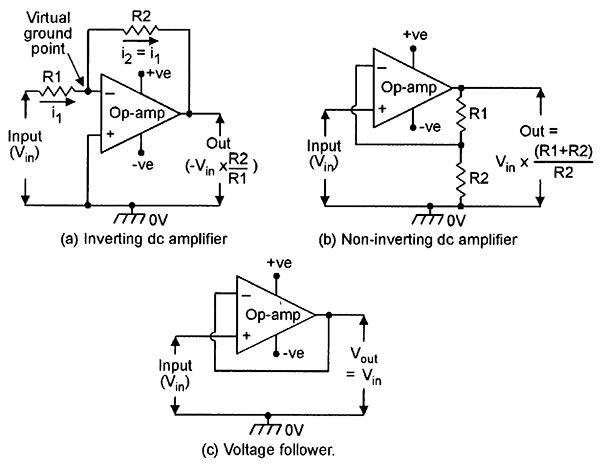 This topic assumes the reader already understands negative feedback around an op-amp - in other words, closed-loop, but if not, the above image from Ray Marston over at Nuts and Volts might help. (courtesy link: https://www.nutsvolts.com/magazine/article/op-amp-cookbook) ------------- That none should be able to park up and enjoy the view without a smartphone and the knowledge in how to use apps |
Posted By: Graham Slee
Date Posted: 27 Jul 2022 at 12:20pm
|
Valve emulation pt.1 The usual method for making an op-amp supposedly perform like a valve is to offset a load on the output to one rail or another. All that does is make the op-amp distort more than it would just driving its normal load. It's supposed to increase the second harmonic distortion, but with all the NFB the open-loop gain affords, there isn't any noticeable quadratic shape indicated by it's output, so the rising distortion must be higher order. To cap it off, the load is usually arranged as a current source, to make the distortion the same at all output levels. However, valve amp distortion falls at lower levels! Most then kid themselves that the op-amp now sounds like a valve. It doesn't! It either sounds the same as an op-amp, or bloody awful. ------------- That none should be able to park up and enjoy the view without a smartphone and the knowledge in how to use apps |
Posted By: Fatmangolf
Date Posted: 27 Jul 2022 at 7:49pm
|
Great explanations, thank you. ------------- Jon Open mind and ears whilst owning GSP Genera, Accession M, Accession MC, Elevator EXP, Solo ULDE, Proprius amps, Cusat50 cables, Lautus digital cable, Spatia cables and links, and a Majestic DAC. |
Posted By: patientot
Date Posted: 27 Jul 2022 at 8:20pm
|
From a quick online search, it looks like "Michael Fidler" on ASR is selling his own phono stage: https://classic-audio.co.uk/spartan10/ - https://classic-audio.co.uk/spartan10/ I'm guessing he wants to bash GS product and "stealth direct" people to his own. I saw this recently on a forum with another product - a special tonearm. The seller created accounts at several forums and was suddenly chiming in on all sorts of turntable related posts while subtly directing various users to their product. In both cases, virtually no one had ever heard of the product being touted or the maker. I've seen this kind of thing in other hobbies as well. In some of those hobbies, the hobbyist forum requires vendors pay for a vendor account that marks their avatar and they are prohibited from posting outside of certain parts of the forum. Of course there are folks that don't want to do this, so they try "fly under the radar" as an ordinary hobbyist. It's all very sneaky and very distasteful behavior IMHO. ------------- SL-1200 MK7 (modified) + Reflex M + PSU-1 used with AT150-40ML, AT VM610 MONO, AT VM95ML, Stanton 680mkII + Ogura, and Shure M35X cartridges. |
Posted By: Graham Slee
Date Posted: 27 Jul 2022 at 8:44pm
|
Valve emulation Pt.2 Due to its fixed nature of amplification factor, it's a sheer waste of effort trying to make an op-amp emulate a triode, but perhaps a pentode? A pentode Gm might be in the order of 1/10th of a BJT (transistor), but doesn't have the gain enhancements of an op-amp, so we could say a pentode voltage amp might do between 1/30th and 1/100th of an op-amp's voltage amp stage (30 - 40 dB less). The LF411 open-loop gain is 106dB, so perhaps a pentode stage could do 66dB to 86dB? (obviously not at the same supply voltage!!) Take an example of 72dB open-loop gain. As linear gain that's 4000, and 1/4000th of 4MHz is 1kHz. So that's where 72dB gain intersects the slope. Right away you see that the open-loop frequency response is far better than DC to 20Hz! It is now DC to 1kHz. So now, we need to reduce the control of NFB on the output swing, so that the output signal exhibits some flatting down on one half cycle - this being due to the offset load from my last post. That should increase second harmonic distortion. 40dB of NFB will exert too much control, but 20dB should be "loose" enough. So, 72dB - 20dB is 52dB or a gain of 400. But that's too much for say a preamp. But it demonstrates how to approach the "characteristics of a pentode." But, we can still pull-off the trick. Say we want a gain of 20dB, that's times 10 and more like preamp level. Then we need add another 20dB such that the open loop gain is 40dB. And once we've made it 40dB, we can simply use the op-amp as normal in non-inverting or inverting mode. We do the 40dB by feeding back the op-amp output via a resistor to its voltage amplifier input. The op-amp's voltage amplifier input is the balance adjust pin connected to the non-inverting differential input's collector, or drain in the case of the LF411. Although it doesn't say which pin, it's pin 5. That resistance appears in parallel with the imaginary 800 Megohms we found earlier in this topic. So, if 800Meg does a gain of 200,000 and we want a gain of 100, then we divide 800Meg by 2000, and that's 400 kilohms. But we know Rin VAS is 4 kilohms, and by 1 + (Rfb / Rin) then 99 * 4 kilohms gives 396 kilohms, 1 + (396 / 4) = 100 So, the pin 6 (output) to pin 5 (VAS input) should be 390k. Using a symmetrical power supply, then you'll want to keep the offset zero, so you also drop a 390k from pin 1 to ground. Both these resistors ought to be 370k because there is 20k already built in (see detailed schematic), but we're playing about after all, and you'll never hear the difference. So here's the circuit.  I will try to find a reference for this. ------------- That none should be able to park up and enjoy the view without a smartphone and the knowledge in how to use apps |
Posted By: Graham Slee
Date Posted: 27 Jul 2022 at 10:16pm
|
I really wanted to acknowledge Walt Jung for imparting such understanding about the open-loop workings of dominant pole op-amps, but I have been unable to locate the PDF online that I wanted to reference. It will be somewhere in the AES records, but I didn't renew my subscription this year so I cannot log-in to search. It used to be on Walt Jung's website too - a typewritten white paper with hand drawn circuit - but such content is sadly gone.
------------- That none should be able to park up and enjoy the view without a smartphone and the knowledge in how to use apps |
Posted By: Graham Slee
Date Posted: 27 Jul 2022 at 10:49pm
All I can say to him is good luck pal! I see he's using me as the "competitor". He's been at it 10 years he says. He may lose the chip on his shoulders after 48 years. And, if you want to make the equivalent of his input stage, try the Genera - it's much cheaper! I see he declares the input stage op-amp is uncompensated, and see the series resistor which stops it reaching unity gain. I hope it's not an OP37 type op-amp. The Genera uses the LF353, noisier but dead fast! One thing he might not comprehend is the market is tiny, so I'd not give up the day job. I like his state-of-the-art residential spare room facility - we all have to start somewhere. But I note he doesn't supply his address which is against the law for a start. As for Classic Audio Ltd, companies house says it is at 64 Old Castle Walk, Gillingham, Kent, ME8 9TZ (Medway like the std. code) And the director's name is Mr Michael John Fearnley, not Michael Fidler. And Michael Fearnley is 28, and lives at 37 North Park,
London,
SE9 5AW - a Tudor style detached property valued at £1.45 million at The Move website. So, if he is Fearnley and not Fidler, then its a case of a rich southerner wanting to steal off a northern working class team. I guess that sums up the north south divide in the UK. ------------- That none should be able to park up and enjoy the view without a smartphone and the knowledge in how to use apps |
Posted By: Graham Slee
Date Posted: 28 Jul 2022 at 12:10am
|
Makes me wonder why somebody would hide behind a fake name and not give his address, and an address is required under UK and EU law on a website selling merchandise to the public or trade. So, as a public service I looked through the companies house info for Classic Audio Ltd, and here are extracts of the companies documents.    In case a customer needs Classic Audio Ltd's details ------------- That none should be able to park up and enjoy the view without a smartphone and the knowledge in how to use apps |
Posted By: Graham Slee
Date Posted: 28 Jul 2022 at 12:16am
|
PS. You can obtain all my business dealings in exactly the same way and plaster it all over the net, but I can save you the trouble. https://companycheck.co.uk/company/09719303/HIFI-SYSTEM-COMPONENTS-LIMITED/ - companycheck.co.uk/company/09719303/HIFI-SYSTEM-COMPONENTS-LIMITED/ https://companycheck.co.uk/company/05637059/GRAHAM-SLEE-PROJECTS-LIMITED/ - companycheck.co.uk/company/05637059/GRAHAM-SLEE-PROJECTS-LIMITED/ https://companycheck.co.uk/company/10417687/GRAHAM-SLEE-PROJECTS-LIMITED/ - companycheck.co.uk/company/10417687/GRAHAM-SLEE-PROJECTS-LIMITED/ https://companycheck.co.uk/director/910913265/MR-GRAHAM-NOEL-SLEE/ - companycheck.co.uk/director/910913265/MR-GRAHAM-NOEL-SLEE/ Because I have nothing to hide.
------------- That none should be able to park up and enjoy the view without a smartphone and the knowledge in how to use apps |
Posted By: discrete badger
Date Posted: 28 Jul 2022 at 8:18am
https://web.archive.org/web/20220000000000* - https://web.archive.org/web/20220000000000* /waltjung.org 181 historical snapshots of his website going back to 2006. I hope you find what you're looking for in one of them.
|
Posted By: Graham Slee
Date Posted: 28 Jul 2022 at 9:18am
|
Thanks for the suggestion but the pdf's won't open and it just sends you right back to the start. Sad.
------------- That none should be able to park up and enjoy the view without a smartphone and the knowledge in how to use apps |
Posted By: lfc jon
Date Posted: 28 Jul 2022 at 6:57pm
|
Had a look at the spartan and I see he's took some of the aesthetics from your phono amps Graham, namely the case work and switches but a different colour LED power on light.
------------- Reflex M, Solo (both with PSU-1) CuSat50, Lautus, Spatia & Spatia links cables. Ortofon Bronze. |
Posted By: Fatmangolf
Date Posted: 28 Jul 2022 at 7:39pm
|
And he didn't state the LED's signal to noise ratio or response in decibels! ------------- Jon Open mind and ears whilst owning GSP Genera, Accession M, Accession MC, Elevator EXP, Solo ULDE, Proprius amps, Cusat50 cables, Lautus digital cable, Spatia cables and links, and a Majestic DAC. |
Posted By: Ash
Date Posted: 28 Jul 2022 at 7:54pm
|
Your frankness and transparency are to be respected Graham. I've always disliked those who make defamatory statements about others in order to forward their own self-interests. Shameful and dishonorable. ------------- We do not see things as they are. We see things as we are. |
Posted By: Graham Slee
Date Posted: 28 Jul 2022 at 8:39pm
Yeah but the single piece extrusion from Lincoln Binns makes it impossible to test the stage inside its box, so we started using a Fischer two piece but their quality was inconsistent, so I asked the West Yorkshire nameplate manufacturer who does the fronts and backs if he could do them, and he got in touch with a Gateshead firm who send 0.25 tonnes of extrusion in 6 metre lengths for him to cut up and anodise, and so we got our own. In all, that took about 20 years. ------------- That none should be able to park up and enjoy the view without a smartphone and the knowledge in how to use apps |
Posted By: Graham Slee
Date Posted: 28 Jul 2022 at 8:55pm
Absolutely surprised about that! We've actually compared S/N using different LEDs and the orange-red one sent out in the Genera kits was the lowest noise, and not only that, but they were an absolute bargain! No, I'm not kidding. I was going to go on about blue LEDs being the most noisy, but all of a sudden my mind flipped to this THD + Noise Sp10 <0.0007%, 35Hz to 22kHz, 9V RMS output, Era Gold V 0.02%, not specified Not specified means at rated output, not 9V r.m.s., so if we use 775mV (0dBu) then 9/0.775 = 11.6, so 0.02 divided by 11.6 = 0.0017%, because it's been dug out of the noise. But then again, avid readers at ASR would know how tests are cheated because they wrote about it recently... ------------- That none should be able to park up and enjoy the view without a smartphone and the knowledge in how to use apps |
Posted By: Fatmangolf
Date Posted: 29 Jul 2022 at 8:05am
|
As you point out his own website shows how 'hifi stats' can be fudged, he then does exactly that by comparing apples and pears, one in the winter and the other in the summer. Unlike HFC there is no information about the test equipment used. Or indeed the location of the company, unless you read the back of his box! ------------- Jon Open mind and ears whilst owning GSP Genera, Accession M, Accession MC, Elevator EXP, Solo ULDE, Proprius amps, Cusat50 cables, Lautus digital cable, Spatia cables and links, and a Majestic DAC. |
Posted By: Graham Slee
Date Posted: 29 Jul 2022 at 9:19am
|
I guess few comprehended anything about "Emerald City" in the 1939 film... I don't envy anybody, but it's on full display that the world of Hi-Fi is coloured green! From a supply side perspective as well as that of many a customer. All I'm doing every day, is trying to develop products that bring musical satisfaction to those who want it. However, in the world of Hi-Fi, that must be stopped! How f*cking childish. ------------- That none should be able to park up and enjoy the view without a smartphone and the knowledge in how to use apps |
Posted By: Graham Slee
Date Posted: 29 Jul 2022 at 9:31am
|
Yes, ignore Graham. Graham must be stopped. Stopped from doing what? 1. Offering products that make people happy (in a world of unhappiness) 2. Sharing knowledge of how it's done. But that's what I do for a living. It's my career. And they want to stop me going to work? ------------- That none should be able to park up and enjoy the view without a smartphone and the knowledge in how to use apps |
Posted By: Ash
Date Posted: 29 Jul 2022 at 10:46am
|
Graham, your previous post seems to sum up society as a whole now. Greedy, miserable and corrupted but masquerading as the polar opposite. I prefer the company of animals to people. How sad is that? "It is no measure of health to be well-adjusted to a profoundly sick society". Give it another few years and the dystopian reality will become clear. People will be too busy on their mobile phones to even care. ------------- We do not see things as they are. We see things as we are. |
Posted By: Graham Slee
Date Posted: 29 Jul 2022 at 12:39pm
|
Education has to be funded. If you want to stop it you remove its funding. Education is the handing down of knowledge - a thing which the older and wiser in a society, do for the younger generations. There is a movement today, that is doing its damndest to prevent the sharing of knowledge. That movement is set up to look like education. I believe ASR is part of that movement, and it does have useful idiots trying to stop that funding. ------------- That none should be able to park up and enjoy the view without a smartphone and the knowledge in how to use apps |
Posted By: Graham Slee
Date Posted: 29 Jul 2022 at 12:54pm
|
They say that private education is wrong and only for the privileged. All I can say is Mexborough in ("Soviet") South Yorkshire was highly privileged. It had a college founded by a Mr Rockingham and a Mr Schofield - both lords I think. It was also funded by private and public enterprises, and us scruffy poor kids from all around Mexborough, received some superb education. Yes, even those who used to be in the "dunce" classes at school. They became mechanics, engineers, typists, nurses - you name it. They made this area strong. But since privately funded education ceased (and the NCB contribution stopped) - well, just look around, and those with sight can see. ------------- That none should be able to park up and enjoy the view without a smartphone and the knowledge in how to use apps |
Posted By: Fatmangolf
Date Posted: 29 Jul 2022 at 4:50pm
|
In the previous post you highlighted a concern I share about reduced funding, the loss of proper education that suits the learner and access to knowledge. There are too many telling and selling 'alternative' truths, making some people miserable as Ash said. ------------- Jon Open mind and ears whilst owning GSP Genera, Accession M, Accession MC, Elevator EXP, Solo ULDE, Proprius amps, Cusat50 cables, Lautus digital cable, Spatia cables and links, and a Majestic DAC. |
Posted By: Ash
Date Posted: 29 Jul 2022 at 6:56pm
|
I think I might have simply given up on hi-fi if GSPAudio hadn't existed several years ago. I would have bought a modest headphone and plugged it into a laptop headphone socket and said "Job done!". I first began reading about hi-fi properly in 2011/2012 and settled on a HD600 for a while because I had absolutely no idea what direction to follow. The AudioEngine D1 I bought for my HD600 didn't provide any improvement in musical enjoyment compared to my laptop so I sent it back for a refund! This place allowed me to genuinely progress onto actual high fidelity equipment and mature my expectations as well. So thanks; thanks for stopping me from going around in circles because I was instead forced to take the advice of those who don't fully know/understand what they are talking about. ------------- We do not see things as they are. We see things as we are. |
Posted By: Graham Slee
Date Posted: 29 Jul 2022 at 10:30pm
|
Fidler has been sent a "cease and desist" informing him that legal action will take place if he carries on in his ways.
------------- That none should be able to park up and enjoy the view without a smartphone and the knowledge in how to use apps |
Posted By: Graham Slee
Date Posted: 30 Jul 2022 at 10:05am
|
Finger nails on a blackboard. Wet polystyrene on glass. You may prefer those sounds as opposed to music, especially if it has a constant deep plodding bass. Yes, it's a trick I've yet to discover - how to take the rhythm section and knock its frequency down a decade or two. The car industry seems to know how it's done - it's programmed into the infotainment section of all modern cars. Hi-Fi does not mean high fidelity anymore. The abbreviation began during the reign of high fidelity, and then forked into falseness, and I know at least one wealthy person who started to make all this happen, but that's my secret and I won't be risking a court appearance. In this topic I will share how some op-amps can deliver a high fidelity performance, while others just do hi-fi tricks. The valve emulation suggestion given earlier is half good and half bad. The bad part is using the op-amp to create a similar distortion to a valve amplifier. Why would anybody want added distortion? If they do, it surely suggests they're tired of the sound their existing set-up gives, and they need to identify the real cause, rather than heading off down silly avenues. The good part of the valve emulation suggestion is the alteration to open-loop gain, which extends the op-amp's open-loop frequency response. The overall negative feedback has fewer errors to deal with. Heavy negative feedback along with open-loop errors shoves harmonics upwards in frequency, and these being unnatural, are heard, even at their low level, whereas lower harmonics sound benign. We already know the "red book" technique to obtain lowest quantisation noise is to shove it upwards in frequency, but artefacts remain, and coupled with greater sized higher harmonics, by the process understood in radio mixer circuits, alien frequencies are generated. In the madness of specmanship, the best measured results often lead to the least musical satisfaction, and it is because such techniques actually cause the problems. It is often the reason why the best Burr-Brown chips are beaten by a lowly cheap op-amp. The written spec is no indication of how the music will sound. ------------- That none should be able to park up and enjoy the view without a smartphone and the knowledge in how to use apps |
Posted By: Graham Slee
Date Posted: 30 Jul 2022 at 1:38pm
|
A precision op-amp usually means DC precision. Op-amps have several more uses than audio, but the uneducated hi-fi nutcase thinks they're all audio capable and it's just a matter of "rolling" them until it sounds "right". To meet the audio specifications which were thought of as being god-sent in the 1970's, Phillips designed the TDA1034. The following is from the New Products pages of Wireless World, September 1976: "Low-noise op-amp A low-noise operational amplifier, designated type TDA1034, has a 10MHz bandwidth and an output drive capability of 10V r.m.s. into a 600 ohm load. This general purpose amplifier has a noise figure of 0.9dB, a slew rate of 13V/μs, and is internally compensated for gains of at least three. An external capacitor, if used to optimize the frequency response, enables the amplifier to be used for a wide range of applications such as studio and recording equipment and telecommunication systems. WW320 (on advertisers reply card) Mullard" That was 46 years ago! It became so popular that a spin-off company, Signetics, made it, alongside other Phillips IC's. Signetics renamed it the NE5534, and I still have one in my collection. The dual version was the NE5533, and later, the unity gain stable NE5532 came about, in an 8 pin DIL plastic package. At 16mA per device, it didn't feature in studio desks half as much as you'd think. The LF353 which came about a few years later got more use! The NE5532 was kept back for the lowest noise mic input channels, and for output stages - due to its output drive capability. My 1992 design of the Canford CCM3 mixer (whilst senior engineer at Audionics) did very much the same. This was because, as studio mixing desk designers, we knew the complexities, the power supply budgets (no, that doesn't mean money but the amount of current), and the effects on stability. As most of Audionics' mixing desks were used in broadcasting, you wouldn't want the outputs oscillating at some high frequency and feeding a commercial or state-run radio transmitter! Sadly, the chip rollers and wannabe manufacturers aren't educated enough to understand such important things. OK, they're not making broadcast gear, but their experiments can lead to instability which reinjects itself into the very same circuit. It can also degrade the performance of equipment it is connected to. Very often those innocent pieces of equipment get blamed for not producing the great sound some self appointed forum guru assures the reader of. ------------- That none should be able to park up and enjoy the view without a smartphone and the knowledge in how to use apps |
Posted By: Graham Slee
Date Posted: 30 Jul 2022 at 2:34pm
|
To achieve the NE5534's 13V/us slew rate, and at the same time, it having a low noise bipolar long tail pair input, required some trade-offs. Natural slew rate hails from emitter degeneration (individual emitter resistors), but that increases noise. The only other way of doing it is by feedforward techniques, or by clever stabilisation. The NE5534 used both, as can be seen in its detailed schematic (a lot of on-chip capacitors). The gain bandwidth plot gives evidence of this enhanced slew rate, by the kink in its roll-off. At some gains, the roll-off vastly exceeded 90 degrees, and should your gain profile just happen to be the same, you'd see a high frequency peak in a spectrum analyser plot. The often used fix was a 22pf capacitor between pins 8 and 5. However, this reduced the slew rate. The eventual NE5532 dual solved the minimum gain (gain of 3) issue, making it unity gain stable. It didn't have any compensation pins, but it managed 9V/us slew rate with what you were given. The noise voltage was higher too. That could only mean that it used emitter degeneration, but the detailed schematic never showed it. What's more, it's manufacturer never published a SPICE sub circuit, but instead offered the NE5534 model. In other words, nobody has ever been able to simulate exactly what's going on with an NE5532 circuit. The result is guesswork, which rests on experience, which you only get from working with the blighters! In professional circuits, the slew rate was further slugged down by using small value capacitors across the NFB resistors, this being felt necessary for stability. We had been instructed (or hinted at) by BBC engineering to use the David Birt (of BBC R&D) two op-amp microphone amplifier which conveniently used the NE5532 dual to generate the antiphase gain. I remember the NFB capacitor values were 10pF, but our chief designer reckoned on 22pf (because it had worked with the NE5534). ------------- That none should be able to park up and enjoy the view without a smartphone and the knowledge in how to use apps |
Posted By: Graham Slee
Date Posted: 30 Jul 2022 at 5:04pm

The problem with a single op-amp instrumentation amp (in-amp), is it's only balanced for unity gain. The problem with a three op-amp instrumentation amp, is the non-inverting side has common mode distortion. The Birt design overcomes all. Reference: Op-amp Cookbook, ADI, plus my own experience ------------- That none should be able to park up and enjoy the view without a smartphone and the knowledge in how to use apps |
Posted By: Graham Slee
Date Posted: 30 Jul 2022 at 7:54pm
|
The Art of Electronics gives op-amp slew-rate by this formula, SR = 0.3mFt Ft is the GBW product, and for an NE5534 it says 10MHz. Without a value for m (we replace it with a 1), and the slew-rate is, 0.3 * 10 = 3V/us The datasheet claims 13V/us at a minimum noise gain of 3. Compensated for unity gain it falls to 6V/us. It would require emitter degeneration of factor m at 4.333 to reach 13V/us, but the schematic doesn't show individual emitter resistors. If it did, its input noise voltage would not be 3.5 nV/√Hz. Degeneration resistors add noise! Therefore, the slew-rate is of the enhanced "feed forward" type. In other words not natural! The NE5532 is compensated for unity gain, has a slew rate of 9V/us, and shares most of the rest of the spec. with the NE5534, except the input noise voltage is now 5nV/√Hz. This would be a physical impossibility without emitter degeneration, yet the same detailed schematic is shown! One can only assume that at the time, even the advanced electronics engineer wouldn't know, and Signetics could keep that aspect a secret. Knowledge, however, was catching up! The Art of Electronics was first published in 1980. It became part of advanced electronics coursework. The NE5532 would have required something like 230 ohm degeneration resistors, causing a noise voltage of around 1.8 nV/√Hz. However, the noise voltage is 5nV/√Hz, and that indicates 1.5 nV/√Hz. A combination of "feed forward" and emitter degeneration looks to be the way it was done. The sound signature of the NE5532 was less pronounced than the NE5534, but it still had one. ------------- That none should be able to park up and enjoy the view without a smartphone and the knowledge in how to use apps |
Posted By: Graham Slee
Date Posted: 30 Jul 2022 at 8:24pm
|
It took the OP275 to start ringing the changes. The noise had risen to 6 nV/√Hz, but the slew rate had reached the dizzying heights of 22V/us. But how? In place of emitter degeneration there was a j-fet input stage (actually j-fet with bipolar transistors) and the reduced Gm of fet's gave the same as you'd expect for bipolar emitter degeneration. Slew rate was becoming more natural, but not quite. The OP275 was quite signatured in its sound. A few manufacturers used it for the RIAA stage, while others stuck with the NE5532 or NE5534. More recently, mobile phone signals have managed to breakthrough bipolar front ends, revealing them to be insufficiently immune for EMC requirements. It resulted in the scramble for low noise FET inputs, with the FET slew rate "screwed down" to achieve the "inky black backdrop". At the same time valve front ends were making a comeback, and nobody cared much about the hiss they caused. This is where I started trying to point out the hypocrisy of it all. What do you want? The most natural sounding music reproduction, or highly signatured sound? Valve front ends had the edge for the natural sound but too much distortion (as well as hiss). The solid-state brigade were barking up the specification tree. I decided to do the natural sound of valves, without the mass distortion, using solid-state, but the downside was valve-like hiss. Thinking about it, I was offering an improvement over both sides! As usual, few bothered to listen.
------------- That none should be able to park up and enjoy the view without a smartphone and the knowledge in how to use apps |
Posted By: Graham Slee
Date Posted: 30 Jul 2022 at 10:40pm
|
The LM4562 and LME49720 dual op-amps were designed, I believe, by the late Bob Pease. Absolutely nothing is known of what's inside, but the LM prefix was always used for bipolar (and LF for FET). With input noise voltage of only 2.7 nV/√Hz it has to be bipolar and no emitter degeneration. Its GBW is 55MHz and slew rate 20V/us. The formula 0.3mFt would suggest 16.5V/us, so I have to guess there is some slew rate enhancement. "Rolled" into an RIAA stage well within its capabilities, the sound was as if something had died. Five years after the LM4562's release, Bob died too. ------------- That none should be able to park up and enjoy the view without a smartphone and the knowledge in how to use apps |
Posted By: Ash
Date Posted: 30 Jul 2022 at 11:01pm
|
I once tried assembling an FM radio circuit kit that used an LM324N quad op-amp integrated circuit. Many years ago now. That and the 741 are the only ones I've used. I always got confused about wiring up -9V on the 741; my electronics teacher was really quite awful. He never explained any of the theory so I didn't fully grasp concepts. What is an operational amplifier? A comparator? It compares the voltage at its inverting input against the voltage at its non-inverting input? At a certain point, it switches from sourcing current to sinking current? ------------- We do not see things as they are. We see things as we are. |
Posted By: Graham Slee
Date Posted: 31 Jul 2022 at 9:21am
|
Hint: when I talk about one op-amp or another, go find its datasheet online and follow what I'm saying. Then you'll understand what I'm saying. Don't just take my word for it.  Here I'm detailing the NE5534 - hopefully for the last time - to show its attributes. 1. It is a three stage op-amp 2. It uses a bandgap reference voltage 3. It has a quasi-complementary output stage 4. It uses "the Shaw diode" 5. The three on-chip capacitors (middle section) show the stability complications Three stage op-amps are notoriously awkward, but for the small supply voltage, they have to cram in as many "gain tricks" as possible to obtain the large open-loop gain that op-amp maths must have. The output stage can be thought of as a miniature Quad 303, because it shares the quasi-complementary output stage and includes the Shaw diode which makes up for the missing PNP emitter follower (EF). The TI datasheet shows the diode as a trans-diode. A trans-diode is simply a transistor configured as a diode with its base and collector terminals joined. Attributes like these demonstrate that this op-amp's main intention was for audio.
------------- That none should be able to park up and enjoy the view without a smartphone and the knowledge in how to use apps |
Posted By: Graham Slee
Date Posted: 31 Jul 2022 at 9:22am
No, it's an amplifier. A comparator is very similar, but a switching device. ------------- That none should be able to park up and enjoy the view without a smartphone and the knowledge in how to use apps |
Posted By: Graham Slee
Date Posted: 31 Jul 2022 at 9:54am
Here's the LF411 for comparison. ------------- That none should be able to park up and enjoy the view without a smartphone and the knowledge in how to use apps |
Posted By: Graham Slee
Date Posted: 31 Jul 2022 at 10:54am
|
The flip flopping of diamond buffers. The diamond buffer started off as a simple transistor assist circuit and to save a lot of faff, you can read all about it here: https://en.wikipedia.org/wiki/Diamond_buffer - https://en.wikipedia.org/wiki/Diamond_buffer There is nothing wrong with a diamond buffer in itself, but there is when it is driven by a resistance. Can you think of a situation where it is driven by a resistance? How about the Ro of an op-amp? All op-amps have Ro. Ro is output resistance. Which way does the current flow? In answering that you will see that the diamond buffer becomes unbalanced - it either wants to flip, or flop to one side. If it had any gain, it would be a disaster! ADI decided to add a bootstrap from output to input of their diamond buffer output stage - a series RC - to compensate for capacitive loads. There are spurious capacitances and inductances in all of electronics. However, for high frequency work, the bootstrapped diamond buffer was OK, because you would not have any low frequencies for say, a video amplifier... Perhaps the data sheet ought to comment on that, but no, it also talks about its DC gain, and so one would think it OK from DC to it's Ft? You'd be wrong. At quiescent, where Ro current flow might expect it to be say outward, then parasitics make it inward, then the bootstrapped diamond buffer flips. However, such parasitics, are influenced by the environment, which is beyond our control, so it then flops. Somewhere between, it might become noisy. Not a problem for a bandwidth filtered video signal. The flips and flops are low frequency. This is my way of saying I got it wrong. Few designers can bring themselves to say that, and instead make out they're always right. Half the AD817 op-amps I bought flipped and flopped and produced noise during their slow transition. ADI could not offer any explanation, suggesting they shouldn't do that. They did take a load back, but were unable to replicate the problem. I don't think they even bothered. Half of them didn't flip-flop and they got used in the Era Gold V. They helped to bring about a fluid sound quality which, depending on the music, had a mesmerising effect, as must have been the intention of the recording. The problem was they were too good. The slew rate of 250V/us and the output current didn't match up at all well for the capacitive loading of the RIAA filter. The bootstrap was there to compensate for such capacitive loading, so I thought I was OK. And boy, did it compensate! And that's where the "shot noise" was coming from, and the rustling where it couldn't "make its mind up". All those op-amps in the bin!! At say 5MHz there would be no noise whatsoever, but related to audio frequencies, even as quiet as it was, it would be there on a good half of the op-amps. So, how to redesign using a different op-amp and retain the subjective performance? As a sub note regarding a similar technology - that of the class AA configurations which do have gain - this is why if the compensation fails, they do flip or flop to one rail or another, and then self destruct! ------------- That none should be able to park up and enjoy the view without a smartphone and the knowledge in how to use apps |
Posted By: Graham Slee
Date Posted: 31 Jul 2022 at 12:09pm
|
The ancestor to the diamond buffer is the transistor assist circuit drawn onto the output of an op-amp illustrated below in the left hand drawing.  You can see its current flow. It is both inward and outward at the same time. Unfortunately, current flows one way! It will try and adopt one direction due to Ro. If beta is increased as in the "speaker driver" right hand drawing, the current gain places even more stress on Ro. The result is oscillation! C comp has to be increased to stop the oscillation, and the slew rate is vastly reduced. This was the monitor hood circuit for the headphone output of a mixer desk. I was asked if I could make it do for a couple of desktop speakers (by increasing output current using the EF2 shown). The result was an oscillator which was quite obvious when connected up to the old Neutrik audio analyser... This tells me something important about the AD817 replacement op-amp - the AD711. It is far better than the AD817 regarding shot noise, but with perhaps one in a hundred, we fail the op-amp ... because of shot noise! As I said earlier, there is no internal schematic of the AD711, but there is of the LF411, and if you add a diamond buffer on the end of an LF411, I think you'd find it identical to the AD711 in many ways. The problem with op-amps is obtaining the output current to drive capacitive loads, and so far, we've seen a number of solutions, that aren't really solutions. ------------- That none should be able to park up and enjoy the view without a smartphone and the knowledge in how to use apps |
Posted By: Graham Slee
Date Posted: 31 Jul 2022 at 12:21pm
|
I think the reader, by now, will realise that the willy-nilly rolling of op-amps is a pastime for the ignorant. The reason why we scrub off the markings of op-amps is because the clever arse forums tell their readers that this or that op-amp is crap, and you should try (flavour of the month). ------------- That none should be able to park up and enjoy the view without a smartphone and the knowledge in how to use apps |
Posted By: Fatmangolf
Date Posted: 31 Jul 2022 at 5:38pm
|
Great stuff. Thank you Graham. ------------- Jon Open mind and ears whilst owning GSP Genera, Accession M, Accession MC, Elevator EXP, Solo ULDE, Proprius amps, Cusat50 cables, Lautus digital cable, Spatia cables and links, and a Majestic DAC. |
Posted By: Graham Slee
Date Posted: 31 Jul 2022 at 8:30pm
|
Op Amp Capacitive Drive The charge formula tells us Q = CV = IT So CV = IT and V = IT/C so V/T = I/C Therefore, as slew-rate (S.R.) is volts per time (V/T) So S.R. = I/C But we now need to make C the subject from V/T = I/C (multiply both sides by C) C * V/T = I (divide both sides by V/T) so C = I/VT then C = I/S.R. And to check sums C * V/T = I (from above) so I = C * S.R. We now have our three formulas to relate current, capacitance and slew rate, S.R. = I/C (1) C = I/S.R. (2) I = C * S.R. (3) If our op-amp circuit is non-inverting, and we ground the input, then the inverting input becomes virtual ground (see noise gain set-up for earlier post). If C is across the NFB, as in such as an RIAA filter, then although it isn't forcing the output down to compromise phase, it is still a capacitive load. The NE5534 has 16mA maximum output current and a slew rate of 13V/us. From equation (2) C = 0.016/13,000,000 = 0.00000000123F That's 0.00123uF, or 1,230pF or 1.23nF (take your pick) That 1.23nF is the maximum value of capacitance that can be allowed from output to input, before all the current is used up, by a fast enough signal, but we still need to drive the load! OK, the input signal isn't going to reach a frequency that requires 13V/us, but we have shown noise gain, a glitch might use up all the current (this being part of EMC immunity and emissions considerations). A value often adopted in NE5534 RIAA circuits is 10nF for the 2122Hz capacitor. Either this is in hope that the input signal isn't all that fast, or the output swing will never reach that specified in the data sheet - or it's in error? The reason for using large value capacitors is to lower the NFB impedance, so that the Rin or divider resistor is made as small a value as possible. Consider that the NE5534 input noise voltage is 3.5 nV/√Hz, and a 1k resistor is 4 nV/√Hz - that doubles the noise at the input. Often, you'll see a value of around 120 ohms which sees an increase of 0.5 nV/√Hz. Hopefully, you can now see why a low noise RIAA has a limited slew rate, and a high slew rate RIAA has more noise! Limiting slew rate does actually lead to early overload on record clicks and pops, which clip the supply, resulting in failure of the negative feedback, which means the clicks and pops get amplified by the open-loop gain. They are massive compared to the music! By going along with the slew rate, the overload is minimised, and the negative feedback stays continuous, which brings the magnitude of the clicks and pops in relation to the music, therefore sounding quieter. It is nothing to do with signal headroom, provided the headroom is sufficient for the signal and its transients. It doesn't have to be several times to accommodate the clicks an pops because they're not as big as some assume! They seem to be big on a sound file, because they have been made big! If they were larger than the largest transients, the groove would be broken over and the record would not play! More to follow... ------------- That none should be able to park up and enjoy the view without a smartphone and the knowledge in how to use apps |
Posted By: Graham Slee
Date Posted: 31 Jul 2022 at 9:53pm
|
You see, one line spin cannot explain the complexities of the workings of an electronic circuit, it never has! So, why does the customer believe one liner marketing spin? OK, it might run to a few sentences, or might fill a page, but we're at page 9, and have only just started exploring the more advanced side of things - the things that make the difference! ------------- That none should be able to park up and enjoy the view without a smartphone and the knowledge in how to use apps |
Posted By: Graham Slee
Date Posted: 31 Jul 2022 at 10:55pm
|
S.R = 2pi f * Vpk We know that on a +/-18V supply, Vpk is 16V (according to TI) So, if the slew rate is 13,000,000V/s, then f = ? f = S.R. / 2pi Vpk = 13,000,000/ 100.53 = 129kHz Checksum 2pi f * Vpk = 2pi 129,000 * 16 = 13,000,000V/s Now, most argue that 129kHz is ridiculous for music, and yes it is, but not many years ago we had cartridges boasting 40kHz, and now we have MI cartridges that can resonate higher than that. It's not about what we hear, it's about the spurious signals generated. Another thing not realised is the rising response of a constant velocity device (the magnetic phono cartridge). High output MC and MI cartridges do resonate high up with high output! So, by ignoring these things, the noise can be brought right down low, but the clicks and pops still annoy. I mean, what the hell is the RIAA stage for? Listening or paper specifications? ------------- That none should be able to park up and enjoy the view without a smartphone and the knowledge in how to use apps |
Posted By: Graham Slee
Date Posted: 31 Jul 2022 at 11:47pm
|
No matter how the RIAA NFB filter is arranged, like the Genera, or with both corner frequency capacitors in series, the result is the same, so the capacitors appear in series even using the Genera configuration. Capacitors in series are like resistors in parallel, so if the LF pole and zero cap is 15nF and the HF pole cap is 4n7, then they sum to approx. 3n6. I will now choose the NE5532 op-amp, which I used to use. It has a slew rate of 9V/uS and 16mA output current. How much current is used at S.R. max.? Using I = C * S.R. (3) The I = 0.000,000,0036 * 9,000,000 = 0.0324A Checksum S.R. = I/C (1), so S.R. = 0.0324 / 0.000,000,0036 = 9,000,000 V/s (9V/us) What is the maximum slew frequency? f = S.R. / 2pi Vpk = 9,000,000/ 100.53 = 89.5kHz So, what if we could be satisfied by a smaller Vpk? Would there be sufficient current for the transients? If ran on 18V (+/- 9V) then Vpk must be around 7.5V (so V r.m.s. will be 5.3V) Then f = 9,000,000 / 47 = 191kHz. So, as a matter of interest, if we decided 89.5kHz was sufficient, then the current would be halved, from 0.0324A to 0.0162A, and so the current just about fits the maximum available current of the NE5532. But how much output current will we need? That depends on what we're driving, and EN 61938 says 22k. 7.5Vpk into 22k is 0.34mA peak! Hive that off the available output current, and the frequency comes down a little from 89.5kHz, to approx. 86kHz. To obtain a gain of 100 (40dB) the divider resistor becomes 180R, which results in noise of 0.72 nV/√Hz. The NE5532 voltage noise is 5 nV/√Hz and we add 0.72 nV/√Hz making 5.72 nV/√Hz. So, at nearly 6 nV/√Hz input noise we are 50% worse than a slugged down NE5534. However, the circuit can drive its RIAA NFB filter and its load to 86kHz up to 7.5Vpk without clipping. OK, we've lost so much input headroom, 5.3V/ 100 is 53mV, and we might as well round it to 50mV because nothing's that accurate. But 50mV is 5 times 10mV, and times 5 is the limit for groove breakover! So, that was the original Gram Amp 2 SE. Customers and reviewers alike commented on the reduced amount of record noise (clicks and pops), and then some smart arse forum got it about that I'd used a "scratch filter". Complete lies, but if you can't follow the physics you'll believe the lies. ------------- That none should be able to park up and enjoy the view without a smartphone and the knowledge in how to use apps |
Posted By: Graham Slee
Date Posted: 01 Aug 2022 at 8:25am
|
It's 40 years since I've done anything with discrete junction field effect transistors (jfets). The only one's left are switching jfets, and we have to thank op-amps for that. Since manufacturers have moved from discrete transistors to "chips with everything", it would seem like the discrete jfet's only use is to switch signals - what a sad demise. However, difet and bifet op-amps still use 'em! Except, they're lithographically laser fabricated onto the same substrate as the rest of the circuitry - they're not discrete. Jfets don't have such high Gm as bipolars, and are more like emitter degenerated bipolar transistors. They have more in common with valves, and are biased in a similar way. The characteristic "degeneration" (which leads to their lower Gm) means they can handle a larger signal swing on their input (gate), and this provides the "m" constant of the op-amp slew rate formula. S.R. = 0.3mFt Remember, a bipolar input op-amp without emitter degeneration means "m" = 1. It might be low-noise, but it's naturally slow. Without a value for "m" a 4MHz op-amp does 0.3 * 4MHz = 1.2V/us. To get slew rate into the teens, it has to be "created" by feedforward techniques in the additional gain stage between long tailed pair and "VAS". By creating slew rate that never existed, as gain naturally rolls down due to bipolar capacitance, it is countered by capacitance. It's a bit like a very high frequency treble control trying to turn up quiet highs. If only we could get rid of that middle stage, and find natural slew rate... Well, we can by using bifet and difet input op-amps. The LF411 is a 4MHz op-amp so its slew rate should be 0.3*4MHz = 1.2v/uS, but it's 15! Therefore, there has to be a value for "m", and 15/1.2 is 12.5, so 0.3*12.5*4MHz = 15V/us. By trading some Gm for the sake of linearity the slew rate becomes naturally large (12.5 times larger). The op-amp no longer needs "the fix" and it follows the simple LTP - VAS - I-amp configuration. Voltage gain is two stage rather than three (and controllable with a single dominant pole). The input stage no longer contains the "rectifier diode" of a bipolar transistor, so cannot rectify radio frequencies so easily. It is more immune and therefore more EMC "friendly". But the noise! Yes, it is noisy compared with a NE5534; 16dB more noisy! Shall we put this into perspective? I was able to obtain 77dB S/N using the NE5532 (slightly more noisy than the NE5534), and with the LF411, that becomes 61dB. What is the accepted dynamic range of vinyl? It is 72dB. 14dB of that is "overload", which leaves 60dB. The IBA (Independent Broadcasting Authority) spec. for record reproducers was 58dB. The LF411 beats that by 3dB. Why would you want 77dB unless you want to boast your paper specification? It isn't about the designer's vanity, it's about the listener's pleasure! 19dB is wasted effort. The analogue noise floor is not the digital noise floor - signals still exist in analogue noise. The designer is given a job to do, and should do that job for his employer - not himself! I have around 50,000 employers. Slew rate trumps noise once the record is playing. A suitable slew rate (in the teens) affords clicks and pops the same courtesy as the music - they're reproduced with the music, rather than being "big out of control bullies". As I've said before, clicks and pops defeat a slow slew rate. Slewing induced distortion is not THD, it causes intermodulation. An audio analyser won't even measure IMD correctly, because its signal generator is unable to adopt a constant velocity output. It hasn't the inductance of a magnetic cartridge. The automation of the APx500 series analyser makes it difficult to place a cartridge in series, but the old ATS-1 allowed it. You gain experience that way, and without experience of your own, you regurgitate the prejudices of others. ------------- That none should be able to park up and enjoy the view without a smartphone and the knowledge in how to use apps |
Posted By: Graham Slee
Date Posted: 01 Aug 2022 at 1:17pm
|
Now we head back to the AD711 datasheet, and read the feature list, and the first (which is the most important) reads, "Enhanced Replacement for LF411 and TL081" The slew rate is just the same as the LF411, and so is its GBW and its noise (note: we always allow a margin so when one datasheet says 15V/us and another says 16V/us, and knowing these are qualified as being "typical", they mean they're near enough the same). So, what's changed? The output current. It is 25mA. The LF411 datasheet doesn't say, but the TL081 indicates 12V maximum output swing into 2k - that's 6mA - and the output stages are sufficiently identical. So, by C = I/S.R., then C = 0.025/16,000,000 = 0.000,000,00156F or 1.56nF. So, if we use the AD711 on an 18V supply, Vpk = 7.35V The frequency is given by f = S.R. / 2pi Vpk, so 16,000,000 / 46 = 347kHz There is no way we'll get anywhere near 347kHz, but let's use the 86kHz from an earlier post, and 347/86 = 4, so that's 4 times 1.56nF, or about 6.2nF. We can use the 15nF + 4n7 capacitors in the NFB, which makes 3n6 approx., and still have current in reserve. What the AD711 has, is more current gain, than an LF411, which means a different output stage.  ------------- That none should be able to park up and enjoy the view without a smartphone and the knowledge in how to use apps |
Posted By: BAK
Date Posted: 01 Aug 2022 at 1:41pm
|
"We can use the 15nF + 4n7 capacitors in the NFB, which makes 3n6 approx." That is in series. ------------- Bruce AT-14SA, Pickering XV-15, Hana EL, Technics SL-1600MK2, Lautus, Majestic DAC, Technics SH-8055 spectrum analyzer, Eminence Beta8A custom cabs; Proprius & Reflex M or C, Enjoy Life your way! |
Posted By: Graham Slee
Date Posted: 01 Aug 2022 at 2:47pm
Yes, and here is a typical application, ------------- That none should be able to park up and enjoy the view without a smartphone and the knowledge in how to use apps |
Posted By: Graham Slee
Date Posted: 01 Aug 2022 at 3:56pm
|
Capacitive loading of op-amps is often identified as 100pf. This is the capacitance which if placed at the op-amp output, will form an RC filter with the op-amp's output resistance Ro. Its corner frequency cannot be prior to its GBW crossing, or it will use up its phase margin and oscillate. It is also a handy way of estimating Ro if the datasheet doesn't say. The highest Fc for an NE5534 is 10MHz, where it crosses below unity gain. Here there's a bit of a cheat because GBW is specified at 10MHz with both 100pf load and a 600 ohm load. The 600 ohm load effectively parallels Ro, and so the calculated Ro will be smaller. From 1/2π f c, 1/2π 10,000,000Hz * 0.000,000,000,1F = 159 ohms Subtract 600 ohms and Ro maximum is 216 ohms. The schematic shows 5 ohm emitter resistors, so this higher resistance must be the intrinsic emitter resistance, but at 16mA it will only add 1.6 ohms. This is a catch-me-out and that's because it's a quasi-complementary, and the collector driven side will be at a far larger resistance. So believe the maths. The reason the NFB capacitance can be so much bigger is because, at the same time as its phase margin is being narrowed, it compensates for that narrowing. It is in effect a large compensation capacitor.  ------------- That none should be able to park up and enjoy the view without a smartphone and the knowledge in how to use apps |
Posted By: Graham Slee
Date Posted: 01 Aug 2022 at 5:36pm
|
For a deeper understanding of op-amp stability search for "Operational Amplifier Stability by Tim Green"
WARNING: The 15 part papers are scattered all over the web and not maintained by TI. You might hit some Trojan sites by accident so ensure your computer and browser are well protected! ------------- That none should be able to park up and enjoy the view without a smartphone and the knowledge in how to use apps |
Posted By: Graham Slee
Date Posted: 02 Aug 2022 at 9:00am
|
If op-amps are so good then why is the internet full of instability cures? (I mean engineering ones) The audio nutter has a tendency to over indulge. I indulge just enough these days... The op-amp with the biggest spec is NOT the best. I understand the word "boast" but does it really impress your friends? (or do they fall asleep?) The top two most grotesque op-amps in my life are the NE5534 and the OP37. Below them are the modern variants that often have a number ending in 34 or 37. Have we not learned of one such "advancement" - LF411 to AD711? Audio amplifiers once had economic importance. In today's world they no longer do. The great advancements in op-amps today are in low voltage 5V single rail types for handheld devices. Those are not Hi-Fi! I doubt we're going to see a cure-all true high fidelity op-amp this side of history. So we have to put up with what we have. In discrete design (transistors) the sensible designer would balk at trying to do what op-amp manufacturers suggest. They all seem to think that we want to drive capacitive loads. The thing is, there have been capacitive loads since "the big bang". You make an emitter follower and it oscillates if connected to a capacitive load, so you isolate it! With what do we isolate it? A resistor! But stating that is treason on some of those audio nutcase forums. Look! loonies exist. They're best ignored (so why am I writing this?) One of the BIG DISCOVERIES in op-amp stability is RISO. RISO is the resistor I just eluded to. Why does common sense fly out of the window when dealing with op-amps? Probably because of the ground swell of nutcases? RISO is hated! An op-amp will drive an 8 ohm headphone direct (NOT), take a look at all the "mint" HPA's. EN 61938 shows how it's done, and it works, but there is no "damping factor", and you must have damping factor! (NOT) (ever taken apart a headphone diaphragm? Has it got any mass worth losing sleep over?) (One exception is the AD823 which is collector output, but there's a catch in there too) So what is the capacitive load? The cable of course! It depends on how long is a piece of cable. The designer doesn't know what you'll use, so he should use an isolating resistor - R iso. EN 61938 gives hints. It can be up to 120 ohms on a headphone output, and up to 2k2 on "gadgets" like phono stages. Only when it comes to the output of a control preamplifier does it get really tough... at 1k. So why not use RISO? This post will be continued after this break ------------- That none should be able to park up and enjoy the view without a smartphone and the knowledge in how to use apps |
Posted By: Graham Slee
Date Posted: 02 Aug 2022 at 10:34am
|
As with all teaching aids, the entire picture is going to be shown up by a resulting plot on a simulator, and you can bet it's going to be only slightly similar to what's shown below. And that's because each point (of inflection) should be a decade away from the next, and good luck with that one!  The point, however, is to stabilise the awkward NE5534 or OP37 for signal gain that hits unity (0dB crossing), because unity gain isn't stable! It isn't stable for the simple reason these op-amps are decompensated and only have stable gains of 3 or above (NE5534) or 5 or above (OP37). So, as Cfb causes the amp to eventually reach a gain of 1, then it collides with the open-loop gain profile where it is -40dB/decade, and goes into oscillation. So, we need to increase the gain so it collides with the open-loop gain profile where it's stable at -20dB/decade. We don't want to interfere with the signal gain, so we do it in noise gain. The provider of the noise gain boosts the gain back up beyond the wanted signal frequency range and somewhere way beyond our hearing, so it doesn't matter. (hint: we can always filter that after Riso) This is why we understand noise gain! It's nothing to do with naughty noise! Now, me not being a teacher (I'm supposed to be a doer), my explanations are crude, and probably don't fully explain, but what the heck! I know what I'm doing, which used to be good enough. But, you know, I've been plagued by clever arses for the past 24 years, who want to get it about that I know nothing, and so I do these technical posts to show that I do know. And maybe at the same time, it might teach the clever arses a thing or two. ------------- That none should be able to park up and enjoy the view without a smartphone and the knowledge in how to use apps |
Posted By: Graham Slee
Date Posted: 02 Aug 2022 at 11:28am
|
(You know? I think I now understand where all this started. It was the day, the hour, the very minute, that a no mark managing director told me I knew nothing about phono preamplifiers! Within seconds my brain computed all the phono preamplifiers I had designed for different purposes, including the understanding of ceramics! Yes, useless ceramic cartridges, which were only used by the top nightclubs before MMs became robust, and before the Technics SL's. Woah! What a sound! OK, I was once told to design a phono preamp for broadcast work. Yes, and that managing director prevented me doing it my way - and yes, the BBC rejected it - but that wasn't my fault. And neither was it my fault that this other managing director had mucked about with the phono preamplifier overnight, and changed things that he didn't understand, only to blame me for it soon after I got in the next morning. So, what do you do? I picked up all my things and left, never to return. I must have known my stuff because within hours he was on the phone making excuses for his behaviour. But the remark had cut deep - really deep - so I told him to get stuffed! Perhaps with all his dealers, he might have thought that one day I may be selling my stuff to them? I don't know, but what I do know, is that all and sundry gave me the biggest negative welcome to the hi-fi industry. Other new kids on the block were welcomed with open arms by the hi-fi press - even if their fruits were second-rate. ------------- That none should be able to park up and enjoy the view without a smartphone and the knowledge in how to use apps |
Posted By: Graham Slee
Date Posted: 03 Aug 2022 at 10:58am
|
The difficulty in using decompensated op-amps in an RIAA stage, is that unity gain is reached at some point. If not unity, then often a lower gain than 3 or 5 WRT the NE5534 and OP37. These are not the only op-amps featuring decompensation, so watch out for so called "recommendations", and get to know op-amps (they're not like valves). Experience shows that phase which is made to "kick back up" to preserve margins, are the op-amps that sound poor. However, that doesn't seem to put off the "rollers". Ignorance is bliss... Headphone amps don't need much voltage gain, often less than 3 or 5 is quite sufficient, so unless you're able to work out the poles and zeros that lead to a stable noise gain, steer clear. Basically, three stage op-amps are going to give you grief. There might be the odd exception, such as a rail to rail device, but is it suited to audio? Op-amps are not exclusively made for audio, but if all you ever do is frequent audio forums, perhaps you'd never know? As an example, one op-amp application I worked on was a HGV rolling road, used to test brakes on tractor units as well as trailers. These op-amps were at times used for audio by some, and they have to go right out to high frequencies to be able to have high voltage gain at DC. These too had to be compensated, otherwise the readings on the meters would be in error. They amplify a tiny voltage from a strain gauge bridge, which shows braking effectiveness. Other uses might be in temperature measurement, and also in medical electronics. Op-amps are often designed with a specific main use, but the manufacturer will also want to sell it into other industries. A decompensated op-amp could be compensated for RIAA use by adding resistance in series with the 2122Hz pole capacitor, but that seriously affects the 20kHz gain, so must be compensated for after Riso, using an RC filter to continue the roll-off. The problem here is the overload margin has to be increased to cater for it. This is why the experienced designer has to way up all things, and choose the most appropriate op-amp. If the designer has to redesign a product to use a different op-amp, then component values change. So, if somebody wanted to "roll in" an AD711 to an AD817 designed Era Gold V, or an AD817 into an AD711 designed Era Gold V, then there will be a noticeable difference in the bass "quantity" as well as quality. If then that somebody preferred one above the other, then that somebody ought to seriously consider tone controls!!! ------------- That none should be able to park up and enjoy the view without a smartphone and the knowledge in how to use apps |
Posted By: Graham Slee
Date Posted: 04 Aug 2022 at 6:45am
|
Passive RIAA Design On a 30V rail an op-amp may be specified to deliver 24V p-p, that's 12V peak, which is 8.4V r.m.s. Much depends on the load it's given. A 5mV magnetic cartridge playing an RIAA LP record will output 50mV at 20kHz, and a 10mV magnetic cartridge at 20kHz outputs 100mV. We know that between 500Hz and 2500Hz the groove velocity can increase up to 5 times before groove breakover, but at 20kHz we know nothing. Do we speculate or do we accept the above outputs as being maximum? We could conjecture using what we know about high frequency groove "wiggle" that it gets tighter and tighter with increasing frequency, especially on the inner end of the groove. And that if modulation were to be 5 times, it might simply just breakover constantly. So what overload value should we give it? Well, there is groove damage because PVC is relatively soft, and readily accepts little cuts from handling, and what is the width of these cuts relative to the HF "wiggle"? OK, perhaps we stick to 5 times overload throughout the frequency range. Therefore, the maximum is going to be 100mV * 5 or 500mV at 20kHz, through considered assumption. The maximum gain of a first stage passive RIAA should therefore be 8.4V / 0.5V = 16.8. And we could EQ the highs after this stage. For the low frequency range we have another 20dB to EQ, and so again the maximum gain is 16.8. In effect, with a 5mV cartridge, we start at 0.5mV and apply two lots of gain at 16.8 times each, which is 282, so the output after two passive EQ stages is 141mV. The last passive filter is unable to drive an "outside world" input such as an amplifier input, so must be buffered, and we may as well apply some gain to get a little more output than 141mV. Now, with a 10mV cartridge, the output will be 282mV, and if we add the 5 times overload, that's 1.41 volts into this last stage. And the maximum is 8.4V, so 8.4/1.41 = 6. We multiply the gains and divide by 10 to find the output for different cartridges. The gain is 169.344. There might be insertion losses which we haven't discovered yet, so decimal point accuracy seems silly. The output for a 10mV cartridge is 1.69 volts - quite impressive! Hope you were following? After the first stage there's a simple RC filter turning over at 2122Hz. May as well use a 7.5k resistor and a 10nF capacitor. The time constant is 7500 * 0.000,000,01 = 0.000075 = 75us (correct!) After the second stage there's a RCR filter turning over at 50Hz, and shelving at 500Hz, so that's a 50Hz pole and a 500Hz zero. Now here is where the passive EQ can get a little bit unstuck. There isn't much charge and discharge current available, so the capacitor needs to have the lowest dielectric absorption we can find. Oh, and its inductance, well it might not have much inductance but we don't have that much current to overcome it. If it's wound, it's a coil, it has inductance, wool over eyes - do not pull! All metal film capacitors are wound because there's no other economic way of doing it, but if slit at 0 and 180 degrees, pressed, trimmed and ends welded, you have slit foil stacked film, which is as inductive as the wires joining it (not very). Now, what about its dielectric absorption (DA)? Yes, insulation can store charge, especially plastics. Wear a nylon shell suit and you'll be discharging all over the place! We want something inert, non stick, but Teflon is very expensive, and difficult to find. Now air would be a great dielectric, but suffers with pollution. Let's try polypropylene. Provided it's not "wound". The limit seems to be 10nF, as any larger it loses its characteristics. So it's 10nF again. So, at 50Hz we need a series resistor of 318 kilohms. Hmm, that's going to have a noise voltage of 1,272 nV/√Hz. And this is low frequency noise, increasing with the inverse of frequency, and then we have the joys of 1/f noise at low frequency. Add to that the fact that we have three non-inverting op-amps following each other and they all have common mode distortion. So, what's any good about a passive RIAA? At this point it isn't worth designing. ------------- That none should be able to park up and enjoy the view without a smartphone and the knowledge in how to use apps |
Posted By: Graham Slee
Date Posted: 04 Aug 2022 at 8:07am
|
Fantastic op-amps with one massive flaw The LF156 (356) and LT1056 feature all the great things you'd ever need in audio, except equal slew-rate. Mr Jung puts it down to the p-channel input stage, and he's probably right, but the output stage - complicated by short circuit proofing - is almost the NE5534 output stage (spot the Shaw diode!). Quasi complimentary outputs like these also have unequal positive and negative slew rates. https://www.analog.com/media/en/reference-design-documentation/design-notes/dn043f.pdf - https://www.analog.com/media/en/reference-design-documentation/design-notes/dn043f.pdf https://www.analog.com/media/en/technical-documentation/data-sheets/10556fd.pdf - https://www.analog.com/media/en/technical-documentation/data-sheets/10556fd.pdf https://www.ti.com/lit/ds/symlink/lf156.pdf?ts=1659534327291&ref_url=https%253A%252F%252Fwww.ti.com%252Fproduct%252FLF156 - https://www.ti.com/lit/ds/symlink/lf156.pdf?ts=1659534327291&ref_url=https%253A%252F%252Fwww.ti.com%252Fproduct%252FLF156 As long as they're made to behave (using "VCCS GOSIT" in simulating the case of the 156/1056), as output stages quasi's can sound great, but you'd not be advised to use a quasi where capacitors are used for EQ. The charge rates differ because the slew rates differ. The audible effects can be minimised by using low DA capacitors, which is why the NE5532 Gram Amp 2 trounced the cheaper NE5532 Gram Amp 1 (the Gram Amp 1 used polyesters). The LF411, however, has near equal slew rate, and just about right for EQ such as RIAA, provided it's high enough impedance (not much output current). Again, the downside is there is no boasting about S/N, but oh, the sound! ------------- That none should be able to park up and enjoy the view without a smartphone and the knowledge in how to use apps |
Posted By: Graham Slee
Date Posted: 05 Aug 2022 at 5:19am
|
Op-amps can work on a single supply too! Or can they? Back in 1974 they were considered to be able to do anything! Yes, just use three "blocking capacitors", input, output, and at Rg - perfect performance every time! A few years ago ADI produced an application note showing the correct way of using op-amps on a single supply. This was in some ways a sales gimmick. OK, it works, sort of. It was to show designers of battery portable items how to utilise op-amps. https://www.analog.com/en/analog-dialogue/articles/avoiding-op-amp-instability-problems.html - https://www.analog.com/en/analog-dialogue/articles/avoiding-op-amp-instability-problems.html Basically, an op-amp is a super high gain power amplifier in miniature, etched and deposited onto a sliver of silicon (a chip or dice - as in diced - sometimes called die). It's housing is called a leadframe (lead as in leadouts). The chip has connection lands, and the lands are connected to the leadframe pins by tiny gold wires. They are gold because gold is inert where other metals suffer dissimilar metal corrosion. The wires are "spot welded" either end - just think what would happen if they were soldered...! After that, they are encapsulated, and the frame cut away from the pin ends. What if you made a single HT power amplifier with only one ground? Let's take that a stage further: what if you made a stereo single HT power amplifier with just one ground? The negative terminal is zero volts on a single supply. The inputs and outputs are held around mid voltage for there to be a symmetrical signal swing. Their DC is blocked by input, output and Rg capacitors. The terminal the gain depends on has also output current flowing in it, but worse than that, it is half wave "rectified" due to how the output capacitor charge is held. But surely, it is of such tiny current that it should not matter? That's how it was with valve amplifiers and they sounded alright. It was only when low impedance transistor amplifiers came into being that the current was more substantial. Yes, but valves are much less complicated, and have less gain by comparison. Once this is realised, the single supply designer might wish to avoid op-amps altogether, and employ discrete design. However, discrete design is a lot more demanding than op-amps. Today, many designers of low level circuits are really op-amp orientated having not done anything discrete. These are well advised to steer clear of single supplies. However, if you're forced into a corner by circumstances, and have to work on single supply op-amp circuits, the downsides have to be mitigated. Would you therefore want a three stage op-amp? Would a simpler op-amp mitigate the situation? Perhaps take advantage of EN 61938 to reduce the output load, yet still make products within the matching system? You would also need to ensure its power supply was optimised for this particular problem. Yes, I am a single supply designer. Would any clever arse like to have a go? I will conclude my contributions to this topic now, but I will be happy to answer any questions you feel are important to you. ------------- That none should be able to park up and enjoy the view without a smartphone and the knowledge in how to use apps |
Posted By: Ash
Date Posted: 05 Aug 2022 at 7:32am
|
Taking your Voyager headphone amplifier as an example then, it uses a 9V PP3 battery. Does the circuit use this supply as +4.5V and -4.5V?
Same with the Solo. The 24V is actually used as +12V and -12V? ------------- We do not see things as they are. We see things as we are. |
Posted By: Graham Slee
Date Posted: 05 Aug 2022 at 9:04am
|
The reason for the outboard DC power supply was to comply with the legislative directives to ensure the legality of my products. The single market economy of Europe and since Brexit, the same standards are adopted by UKCA, requires mains powered equipment to meet certain standards, and it is the manufacturers responsibility to ensure safety. An outboard power supply approach, where that power supply meets with safety standards, is often used, and sometimes the responsibility is passed, third party to the power supply manufacturer. It is very difficult to circumvent the law. Not that I want to circumvent it, I actually proved the PSU1 through a certified international standards body: Kema Quality B.V., in the Netherlands. As such, the power supply of our own manufacture was certified as compliant with CE marking and that also meets with UKCA. However, in the EC and UK, and many other countries, the manufacturer can self certify the safety of its mains powered products by declaring the relevant standard has been applied. I got my certification to please a complaining Canadian distributor. The items thus powered become Separated Extra Low Voltage (SELV), which means they're safe? They're only safe electrically if they do not compromise the external power supply. There are other safety aspects such as sharp corners etc. A plug-top transformer might be used to provide a.c. to an a.c. powered SELV item. However, that combination must meet with the emissions part of EMC law. If the SELV item contains a CIF rectifier (capacitive input filter) then substantial harmonics exist between the SELV item and the plug-top transformer, and the (usually) 5 foot bell wire low voltage cable becomes a transmitter of the harmonics. That contravenes EMC emissions legislation. The rectifier switches transformer current to the CIF for approximately one sixth of each half cycle. If half a cycle is classed as 100Hz, the switching lasts for approximately 600Hz per 100Hz to put it crudely. The plug top transformer's primary sees two inductances, its on-load inductance and its off-load inductance. The eddy current effect sets up a kind of oscillatory action described as harmonic current. The approx. 5ft wires (or any length for that matter) are a continuation of the transformer's secondary. The harmonic pulses travel along these wires and will radiate as an electric field, which is an emission. Such a.c. power supplies only meet EMC when supplying an a.c. load. A CIF rectifier filter is not a purely a.c. load. The use of a DC external supply to power DC apparatus, does not emit these harmonics, because the harmonic path is contained within the power supply unit. If the paths from transformer via rectifier to the CIF are short, the harmonic current cannot develop much if any emissions in its internal wiring. The use of an E-I laminated transformer within the power supply assists the reduction in harmonics due to its primary magnetising current "swamping" the inductive effect on magnetising current, acting as a brake on transformer harmonics. As such, the DC power supply is better able to comply with emission levels than an a.c. supply with a CIF load. ------------------------------------------------------------ Reference: EFFECT OF TRANSFORMER LEAKAGE INDUCTANCE ON CAPACITIVE INPUT FILTERS https://apps.dtic.mil/sti/pdfs/ADA637782.pdf - https://apps.dtic.mil/sti/pdfs/ADA637782.pdf ------------- That none should be able to park up and enjoy the view without a smartphone and the knowledge in how to use apps |
Posted By: Graham Slee
Date Posted: 05 Aug 2022 at 11:08am
Ash, An op-amp, if it were a thinking being, wouldn't know if it had +/- or just +.  It doesn't have a pin marked 0V, just positive and negative - a bit like a torch bulb. An EMF is supplied across it and if it requires 9 volts, then it's either +9V with respect to the negative terminal, or -9V with respect to the positive terminal. If you want it to output a signal placed such that the signal is centred between zero and +9V, you make the output +4.5V. You can do that by two equal resistors in series across the 9V, and connect the midpoint to its non-inverting input, and provided they match the feedback resistor, the op-amp will sit at +4.5V. As an example of "match": if the feedback resistor is 100k ohms, the two resistors are 200k ohms each. Why? because the two resistors of a potential divider are effectively in parallel. Their centre point is mathematically 4.5V, the op-amp output is 4.5V, the inputs won't be because they require bias current, and the same bias current is used by each input, so each input voltage is the same. With a high bias current input, the input voltage might be several millivolts up or down depending on the direction of current flow to/from the inputs, or with a low bias current, you'd probably swear it was 4.5V. Or, You can use a split supply that has a mid rail which you call 0V, and just "drop" one 100k resistor to the non-inverting input. Perhaps your teacher had other things on his/her/its mind? Was it a mixed class, or perhaps it was politics.... The problems start when you've to divide voltages to obtain gain. With a mid rail you drop say a 10k resistor from inverting input to the mid rail (0V) to get a gain of 11 ( 1+(100k/10k) ), and then you notice the output has offset one way or the other. So then you have to make the resistance to the other input have 100k in parallel with 10k (or a 9.1k resistor), but then 9.1k is a too heavy load for your input signal - you wanted 100k. OK then, that's easy. Break the current path between the 10k and 0V with a capacitor. The op-amp then reverts to a 0V (still really 4.5V) output. But often, the capacitor needs to be a large value which means electrolytic, and these should be polarised right way up. Yes, but all capacitors are bad, so we'll make a rod for our backs and use another op-amp to make a servo to force first op-amp to do what it really didn't want to (this part not shown in diagram). ------------- That none should be able to park up and enjoy the view without a smartphone and the knowledge in how to use apps |
Posted By: Graham Slee
Date Posted: 07 Aug 2022 at 6:24am
|
Regarding the "which way up?" comment on my last diagram, it depends on whether the op-amp input is NPN, PNP, N-channel or P-channel. If it is NPN or N-channel, current flows inward so there is a voltage drop across the input resistor, and so the input is negative to the 0V mid-rail. As both inputs are made identical by op-amp law, then the capacitor shown is wrong way up. If it is PNP or P-channel, current flows outward so there is a voltage rise across the input resistor, and so the input is positive to the 0V mid-rail. As both inputs are made identical by op-amp law, then the capacitor shown is right way up. The amount of voltage drop or voltage rise depends on the input bias current and the input resistance (by Ohm's law). An electrolytic capacitor is a polarised device and is marked as such. Values as high as 1000uF have featured in at least one RIAA stage I have seen. Initial leakage is 0.01Q + 3(uA) for most sub 100V electrolytics. The initial leakage adds to the charge time constant, extending the time it takes to charge the capacitor. I'm not going into the cumbersome maths here, but I'd be surprised if the capacitor's leakage will be overcome in a single listening session! Now, if it had a decent voltage across it? The single rail application provides that "decent voltage". And then, if an "op-amp roller" replaces the op-amp from NPN or N-channel to a PNP or P-channel (or vice versa), then what? I'm sure there'll be a difference in how it sounds... ------------- That none should be able to park up and enjoy the view without a smartphone and the knowledge in how to use apps |
Posted By: Graham Slee
Date Posted: 08 Aug 2022 at 6:50am
|
Long ago, 50 years ago, there was a thirst for knowledge like this. Quite a lot of people were thankful for it. ------------- That none should be able to park up and enjoy the view without a smartphone and the knowledge in how to use apps |
Posted By: Fatmangolf
Date Posted: 08 Aug 2022 at 7:41am
Thank you again for this information. Why do you think DIY is dead, please? ------------- Jon Open mind and ears whilst owning GSP Genera, Accession M, Accession MC, Elevator EXP, Solo ULDE, Proprius amps, Cusat50 cables, Lautus digital cable, Spatia cables and links, and a Majestic DAC. |
Posted By: gwebster
Date Posted: 08 Aug 2022 at 10:52am
I'm still doing lots of DIY electronics. While my current audio setup includes my Bitzie DAC paired with a Raspberry Pi, a commercial CD player and FM tuner, the phono (replacing my Genera phono), pre-amp, digital remote controller and power amp are all strictly DIY. I've been avidly following this thread and have been making use of the formulae to verify elements of my phono circuit based on Graham's patented phono architecture (patent stuff is OK to apply to personal use but not for commercial without paying a license fee, I understand). ------------- Inspire Apollo tt, O/L modded RB250, Ortofon 2M Black, Slee Different Approach inspired Phono, Putzeys Pre, Cusat, Raspberry Pi/Volumio, Bitzie, Self Load Invariant Power, Acoustic Energy AE509s |
Posted By: Graham Slee
Date Posted: 09 Aug 2022 at 7:23am
|
Perhaps it's the way I tell 'em... But I don't think there's anything like the clamour for learning from the ground up. Half way through the movie perhaps, but not the fundamentals. By half way through the movie, I mean, taking an existing item and playing about with it. OK, there may be nothing wrong with that. I guess it could be something to do with my age and my frugal upbringing. Starting out at zero seems to be dead, as in not interesting. I do see a few members here having a read - probably two, three, or maybe up to five. It's indicated in brackets after the main forum title, but it could be any of its topics, maybe not this one. We used to have members who wanted more DIY, so I offered what I could, and I haven't seen them since! (many years in-fact) Perhaps it's the wrong DIY? I can only try and share what I know, and what I know has led to the things folks buy from us, and they seem popular enough. I must admit to being an analogue man, and I know this is a digital world (cue for a song?), so maybe that's why I feel very few have any interest? By dead, I mean dead in spirit (enthusiasm). ------------- That none should be able to park up and enjoy the view without a smartphone and the knowledge in how to use apps |
Posted By: Graham Slee
Date Posted: 09 Aug 2022 at 7:38am
Correct! And it is encouraged - the personal use part (that's the spirit of invention/discovery/whatever). It's all part of the learning spiral, and as we ascend that staircase we come back around and start seeing things a little differently, and maybe through the lessons we learn, we can make it a little better each time. How many widgets lay at rest in coffins? What benefit did those widgets bring to anyone? ------------- That none should be able to park up and enjoy the view without a smartphone and the knowledge in how to use apps |
Posted By: Fatmangolf
Date Posted: 09 Aug 2022 at 7:38am
|
Yes I see your point about fewer people building from scratch as compared to modifications, thanks Graham. ------------- Jon Open mind and ears whilst owning GSP Genera, Accession M, Accession MC, Elevator EXP, Solo ULDE, Proprius amps, Cusat50 cables, Lautus digital cable, Spatia cables and links, and a Majestic DAC. |
Posted By: gwebster
Date Posted: 09 Aug 2022 at 8:46am
I'm glad to hear my patent interpretation was correct! I wouldn't want to have offended you by infringing your legal rights. While my "Slee inspired" phono stage is a delight to me, I'm sure it still has a way to go to match the Accession. ------------- Inspire Apollo tt, O/L modded RB250, Ortofon 2M Black, Slee Different Approach inspired Phono, Putzeys Pre, Cusat, Raspberry Pi/Volumio, Bitzie, Self Load Invariant Power, Acoustic Energy AE509s |
Posted By: Ash
Date Posted: 09 Aug 2022 at 10:10am
|
https://youtu.be/OkQlrIQhUMQ - https://youtu.be/OkQlrIQhUMQ ------------- We do not see things as they are. We see things as we are. |
Posted By: BackinBlack
Date Posted: 09 Aug 2022 at 12:14pm
|
In my early yoof, I used to design and build in the latter days of valves and the new fangled germanium transistors. Then University and earning a living distracted me. Earned a living by applying my skills to digging holes in the ground, then developing and applying machines for digging large holes through the ground. Detailed electronics design became other peoples problems, I just developed the concepts. Nowadays I find that although I have retained the basics, a lot of the detail design whilst interesting is not something I can "do" anymore. Physically building electronic devices still interests me, but I leave the electronics design to those who can. Much of my enjoyment these days comes from designing, building and flying large model aeroplanes, the camaraderie at the flying field is also a great pleasure. So that's my take on the current level of interest in designing and building Electronics! ------------- Just listen, if it sounds good to you, enjoy it. |
Posted By: Graham Slee
Date Posted: 09 Aug 2022 at 3:24pm
|
A true Fidler ------------- That none should be able to park up and enjoy the view without a smartphone and the knowledge in how to use apps |
Posted By: Fatmangolf
Date Posted: 09 Aug 2022 at 6:47pm
|
This made me smile but seems a little harsh on JW! And slightly off topic. ------------- Jon Open mind and ears whilst owning GSP Genera, Accession M, Accession MC, Elevator EXP, Solo ULDE, Proprius amps, Cusat50 cables, Lautus digital cable, Spatia cables and links, and a Majestic DAC. |
Posted By: Graham Slee
Date Posted: 09 Aug 2022 at 8:49pm
|
The works of Joseph Fidler Walsh have been amongst my favourite music, and get more plays in my workshop than many. I first heard his music on a pal's bedsit system using a Teleton SA206b amplifier. The album: "So What" (1975, in 1975). I have twelve of his albums including his time in The James Gang. All as FLACs plus early albums on vinyl too (and the Eagles' "Hell Freezes Over"). Every audio stage I've ever designed since 1975 has been auditioned playing his music (among others). I've never heard any of it live, but used to try and play Turn To Stone (badly) on an old acoustic - obviously without fuzz. My fret fingers were too slow, so I decided on a technical career instead. I think if tracks like "Midnight Man" reproduce nicely and the intense fuzz doesn't fracture your hammer, anvil, and stirrup, but you are able to hear the inflection in Mary Sterpka's voice, and her harmonies with Joe, then a design might be right.  ------------- That none should be able to park up and enjoy the view without a smartphone and the knowledge in how to use apps |
Posted By: Fatmangolf
Date Posted: 09 Aug 2022 at 9:52pm
|
We played the second James Gang LP last week. Great music and a good test of the op amps, I agree. ------------- Jon Open mind and ears whilst owning GSP Genera, Accession M, Accession MC, Elevator EXP, Solo ULDE, Proprius amps, Cusat50 cables, Lautus digital cable, Spatia cables and links, and a Majestic DAC. |
Posted By: RichW
Date Posted: 10 Aug 2022 at 10:45am
Designing, building and flying model aeroplanes is a fantastic & fulfilling hobby Ian. I must start it up again.  There's an analogy here with the 'DIY' aspect mentioned earlier. These days the majority of model flyers buy pre-built ('ARTF') models - for various reasons - cost, time, skill etc. and there is a decline in those who build from scratch. Go back a few decades & it was frowned on if you didn't carve your own propellors! ------------- Majestic/Enigma, Accession MM & MC. |
Posted By: Graham Slee
Date Posted: 10 Aug 2022 at 11:59am
|
I don't know which way I should take these comments. It's pretty safe offering an op-amp based phono stage design (the Genera), because there's little to go wrong. The op-amp can take some "abuse" and still retain its performance characteristics. It has quite a bit of built-in protection. But a power amplifier carries a lot more risk. I know this from my "first time" when I switched-on and it didn't work, and I knew squat to be able to fix it. OK, that was a very long time ago, and it didn't put me off my designing career. Now, except for one silly little accident, the 70's power amp has survived through hundreds of modifications. It's not because it's fool proof but because I knew what I was doing. It can take quite a bit of abuse, but it cannot withstand changes to its fundamental design. By changes, I mean a misplaced component where it matters the most. And how would you know if you didn't understand the circuit? To offer it as a parts kit, I realised I must write a manual to provide that understanding, and it's at 136 pages so far. Recent comments are a bit unnerving. It isn't about carving your own propeller, but it's about stability, and safety of the amplifier as well as that of the constructor. It isn't a cheap parts kit either - the parts are expensive - and the labour in packing it is expensive because of the responsibility of getting it right. It's not something that can be automated, simply because it will never go mass market. We're talking about ones or twos. So please don't take offence, but the things I've been asked for I am unable to do as painting by numbers. I can only do it like a constructional article, and constructional articles about discrete circuitry tend to assume some level of knowledge and competence. I like to share knowledge and I'm a giving type. Will somebody tell me it isn't all in vain? ------------- That none should be able to park up and enjoy the view without a smartphone and the knowledge in how to use apps |
Posted By: BackinBlack
Date Posted: 10 Aug 2022 at 3:54pm
|
Graham, my comments were not meant to be disparaging, sorry if they seemed so. I have thoroughly enjoyed your dissection, re-evaluation and dissertation on making the 70s design work as intended. Some of the analysis took me a little time to understand, but understand I did. I have generally made it a principle to know how things work and what can be done (or not done). Whilst I may not have been actively involved in audio design and construction, I have completed many other electronic projects allied to my other interests. I understand your "painting by numbers" comments regarding the assembly of the amplifier. I consider myself more than capable of building the "kit" in a safe and competent manner, even though I haven't carved a propellor since my days at school! I certainly don't think you're wasting your time. Ian ------------- Just listen, if it sounds good to you, enjoy it. |
Posted By: Fatmangolf
Date Posted: 10 Aug 2022 at 5:29pm
|
FWIW I thought the 1970's amp and transformer design thread was brilliant work and take your point about the manual. ------------- Jon Open mind and ears whilst owning GSP Genera, Accession M, Accession MC, Elevator EXP, Solo ULDE, Proprius amps, Cusat50 cables, Lautus digital cable, Spatia cables and links, and a Majestic DAC. |
Posted By: RichW
Date Posted: 11 Aug 2022 at 8:58am
|
Oops no, comments made about aeromodelling were just intended to illustrate the general decline in DIY. Personally, having had previous experience of DIY audio electronics the kit is of great interest & it would hopefully also be to many others. Your difficulties in writing a manual are understandable but your work isn't in vain. (Incidentally carving a prop isn't easy & a badly made one can be dangerous. )------------- Majestic/Enigma, Accession MM & MC. |
Posted By: gwebster
Date Posted: 11 Aug 2022 at 11:09am
As an electronics DIYer, I'm happy to design op-amp based phono and pre-amps from scratch (not to Graham's standard by any means) using all the freely available software tools available on the web.
Back in the day, I wouldn't have had anything like this available to me and had to use a slide rule or calculator while doing circuit design work, sticky tape and transparent film for circuit layout and play around with nasty chemicals to etch my own boards as there weren't any cheap Chinese PCB sources available . I certainly wouldn't tackle a power amplifier. Last time I did that (trying to emulate the Quad 303), all I did was get magic smoke from several sets of power transistors. Hats off to Graham! ------------- Inspire Apollo tt, O/L modded RB250, Ortofon 2M Black, Slee Different Approach inspired Phono, Putzeys Pre, Cusat, Raspberry Pi/Volumio, Bitzie, Self Load Invariant Power, Acoustic Energy AE509s |
Posted By: Graham Slee
Date Posted: 11 Aug 2022 at 4:17pm
Back in the day before simulators, some designers worked "blind" and perhaps expected miracles... They would, I assume, have had a better education than I, but in the 303 schematic, I can see some similar mistakes that always seemed to result in click-bang-smoke. It was always a good idea to stick with the 2N3055"H", but eventually the instability penny dropped - it had to after they took the "H" away - either that or change career. There became a fear of second breakdown (the "H" didn't have one), and stability criteria had to be learned (both HF and thermal). After which it didn't seem so bad. Still, and I must admit, I half grasped the HF stability part due to my lack of mathematical "tools", but after gaining them things looked so easy (slight sarcasm warning). When the 405 came out, I swear I could here the distant shouts of "Jonah!" ------------- That none should be able to park up and enjoy the view without a smartphone and the knowledge in how to use apps |