Azimuth meter
Printed From: Graham Slee Hifi System Components
Category: DIY AUDIO
Forum Name: Owner's Hot-Mods
Forum Description: Tell us how and why you hot-modded your audio gear
URL: https://www.hifisystemcomponents.com/forum/forum_posts.asp?TID=1845
Printed Date: 27 Mar 2026 at 2:12am
Software Version: Web Wiz Forums 12.01 - http://www.webwizforums.com
Topic: Azimuth meter
Posted By: Fatmangolf
Subject: Azimuth meter
Date Posted: 22 Apr 2013 at 9:35pm
|
Just wanted to share a bit of DIY: I am building a stereo crosstalk analyser using the AD8302 RF/IF chip. I based the schematic on the datasheet and adapted it to work at audio frequencies not Mega Hertz. In short I've breadboarded a device that will be in a box later this week as follows:
2 phono sockets to connect my turntable via the phono preamp Analogue meters for left channel separation (LED comes on), right channel separation (different LED comes on), and phase difference. The range is +/- 30dB (adjusted to 20 or 40dB with a switched attenuator on one channel only) for measuring crosstalk and 0-180 degrees on phase difference. If anyone's looking at the datasheet I wired the left meter from Vmag to Ground and the right from Vref to Vmag. The 1.6V low current LEDS block the reverse current flow to protect the meters and bring them in from about 20dB when the diode conducts. And they look pretty. The phase meter is wired from Vref to Vph. The AD8302 is 14 pin SMD needing few external parts, I used 22uF caps for the input and offset decoupling, giving about 100Hz as the corner frequency. After construction and calibration for +30dB FSD on each meter I plan to use the meter to fine tune the azimuth on my turntables using a test LP that has test tracks with 1kHz on only the left and right, respectively. I will note the changes to maximise and equalise the L-R and R-L separation, whilst minimising and matching the readings for phase difference. I will also be listening carefully to ensure aligning the coils coincides with aligning the stylus. If anyone is interested I will post a schematic and some photos? ------------- Jon Open mind and ears whilst owning GSP Genera, Accession M, Accession MC, Elevator EXP, Solo ULDE, Proprius amps, Cusat50 cables, Lautus digital cable, Spatia cables and links, and a Majestic DAC. |
Replies:
Posted By: BackinBlack
Date Posted: 22 Apr 2013 at 10:46pm
|
Sounds interesting. A novel application that could prove really useful. Cartridge set up is something akin to a black art, this should counter some of the apparent magic (ie guesswork!). More info would be good, I look forward to seeing the development and your results. Ian. |
Posted By: tg [RIP]
Date Posted: 23 Apr 2013 at 7:33am
|
A sort of DIY Fosgometer then. Bit beyond my DIY skills (or electronic knowledge FTM) but certainly interesting. Piccies are always good :) |
Posted By: Fatmangolf
Date Posted: 23 Apr 2013 at 10:21pm
|
A bit like it but the phase measurement is different. Balancing that as well should improve the stereo.image with stable positioning and width. I'll draw a schematic and photograph the pcb. ------------- Jon Open mind and ears whilst owning GSP Genera, Accession M, Accession MC, Elevator EXP, Solo ULDE, Proprius amps, Cusat50 cables, Lautus digital cable, Spatia cables and links, and a Majestic DAC. |
Posted By: JamesD
Date Posted: 23 Apr 2013 at 10:40pm
|
Sounds interesting, will have a look at your schematics if you post them. Always good to have some means of confirming what you think your ears are telling you! ------------- Aren't ears brilliant |
Posted By: Fatmangolf
Date Posted: 24 Apr 2013 at 10:05pm
|
This is the datasheet: http://www.analog.com/static/imported-files/data_sheets/AD8302.pdf - AD8302 datasheet On page 16 you'll see the schematic. For 1kHz test LP tracks the input caps C1/4/5/6 are all 22uF polarised and I used a spare 470uF for C2. For the left signal separation I wired a 250uA meter in series with a 1.6V LED and a 1k preset pot, connected from Vmag to 0V. For right the same but wired from Vref to Vmag. Please note that +30dB (approx. 200mV ac on L/6mV ac on right) and -30(6mV and 200mV, both ac) give 1.8V and 0.03V. I adjusted the presets to full meter deflection at +/- 30dB. +35dB or more overshoots the 1.8V stated limit on Vmag to give about +1.95V. It's the phase difference on crosstalk (i.e. from the active left channel to the almost silent right channel, or vice-versa) that adds another dimension to azimuth adjustment. If you've done this with a dual channel oscilloscope (or software equivalent) you'll know why! I will draw the schematic I've built and photograph the circuits at the weekend. This is simply using a production IC and schematic but for a different use. Once I spotted the potential application I did search online to see if someone had already done the fine tuning. ------------- Jon Open mind and ears whilst owning GSP Genera, Accession M, Accession MC, Elevator EXP, Solo ULDE, Proprius amps, Cusat50 cables, Lautus digital cable, Spatia cables and links, and a Majestic DAC. |
Posted By: Fatmangolf
Date Posted: 29 Apr 2013 at 9:25pm
|
The unit does work but the metering on L and R channel separation is less linear than I would like. In reality connecting one digital voltmeter to the Vmag (channel level difference) and another to Vph for the phase difference is more precise. After trying various resistors in series with and in parallel to the level meters, I am reconsidering a larger meter with the midpoint. The aim was to design a self-contained unit for level and phase so I will persevere when I next have time. I can confirm that the IC works fine at audio frequencies and works with only a few extra parts. I ran a 22k resistor from each phono socket to the dc blocking capacitor on that IC input. That took the 300mV coming from the phono preamp down into the log detector's midband, see the datasheet for more details. ------------- Jon Open mind and ears whilst owning GSP Genera, Accession M, Accession MC, Elevator EXP, Solo ULDE, Proprius amps, Cusat50 cables, Lautus digital cable, Spatia cables and links, and a Majestic DAC. |
Posted By: Fatmangolf
Date Posted: 02 May 2013 at 8:55pm
 The finished unit. The meters are Left separation, phase difference, and Right separation. The switches are on/off and the Left +6dB/neutral/+6dB right. 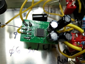 I used a Farnell 14 pin adaptor board and realised I could get the 22uF caps and the links between pins 9/10 and 12/13. I built it quickly and took it off the breadboard and into the box with fast point to point wiring. It works and the preset pots on the L/R meters allowed me to balance FSD on the signal meters. I miss the precision of a DMM on the 2V scale and will add terminals for this. ------------- Jon Open mind and ears whilst owning GSP Genera, Accession M, Accession MC, Elevator EXP, Solo ULDE, Proprius amps, Cusat50 cables, Lautus digital cable, Spatia cables and links, and a Majestic DAC. |
Posted By: Fatmangolf
Date Posted: 02 May 2013 at 10:19pm
|
Use of the device: Azimuth adjustment means altering the angle of the stylus/cantilever and coils or magnets, trying to get the cartridge vertical in the groove. Unfortunately the mechanical and electrical parts may not be perfectly aligned. Look at the cartridge straight on and imagine rotating it clockwise or anti-clockwise. If you headshell or arm fitting allows this then you can experiment with the azimuth. The standard azimuth test is to put a mirror under the cartridge and check the cartridge and its reflection match. Or make sure the turntable plinth is level then put small spirit level on top of the headshell, adjust the azimuth for level. Beyond that you can adjust for the best sound, listening for width of the soundstage and clarity of instruments across it. Or use a multimeter on your preamp outputs (or the speakers - use earplugs as M.Fremer suggests) and play a test record with left signal only and right signal only tracks. On the Left only track there will be some spillage onto the Right side or crosstalk, and vice-versa. Measure the Left to ground and Right to ground level for both tracks, It's the relative levels or separation that you're measuring but be aware that not all cartridge are perfectly balanced so one channel may be louder whatever you do. This also means that adjusting azimuth so the left and right only signals are the same level may not give perfect azimuth (or anti-skate setting). If you're still reading you can use the voltmeter measurement of separation and then listen for the clearest sound. My experiment with phasemeter was about the phase of the dominant left channel to the crosstalk on the right. I have read that minimising the L-R (and R-L on Right only track) phase difference sounds best. My setup showed the lowest and similar phase differences at the same azimuth as the maximum separation, which also matched. Inevitably it was really close the vertical position I found with spirit level earlier. You'll need to draw a table where you write channel level and phase difference on the Left only and Right only tracks. Take these measurements for each incremental step on azimuth. I took a shortcut and measured the level headshell followed by slightly ACW and slightly CW. You could run through a series of steps. If you want to experiment and make it repeatable you will need a tubular spirit level so you can roughly measure and note the azimuth angle between headshell angle and level. I used one of the keyring levels Maplin sell for £1. It works but is imprecise. I considered a more sophisticated version with a longer tube sourced on the Internet but the sun came out... Obscure point: the offset angle on most arms means that rotating the arm at the pivot to adjust the azimuth also alters the cartridge alignment slightly. Like arc alignment, VTA/SRA and VTF, it's all linked. Not much to be fair. Like the standard height/arc/downforce/bias settings your sound will improve if you get the azimuth right, but it may be fine tuning IMO. In conclusion if it sounds good it probably is good. ------------- Jon Open mind and ears whilst owning GSP Genera, Accession M, Accession MC, Elevator EXP, Solo ULDE, Proprius amps, Cusat50 cables, Lautus digital cable, Spatia cables and links, and a Majestic DAC. |
Posted By: Fatmangolf
Date Posted: 08 Jul 2013 at 10:37pm
|
It has moved forward a bit. I've disconnected the panel meters and fitted 2mm sockets for Vmag, Vphase and 0V. I am trying a -15dB attenuator at the moment which will move Vmag for typical cartridges into the flatter part of the IC's curve. My overall approach remains the same. The optimal electrical azimuth should be where the inter-channel crosstalk is minimised and equal and the phase differences are equal. Ideal if the cantilever/stylus are aligned with the electromagnetic system. ------------- Jon Open mind and ears whilst owning GSP Genera, Accession M, Accession MC, Elevator EXP, Solo ULDE, Proprius amps, Cusat50 cables, Lautus digital cable, Spatia cables and links, and a Majestic DAC. |
Posted By: Fatmangolf
Date Posted: 10 Jul 2013 at 10:03pm
|
The Vmag starts at around 900mV for an equal L and R signal input, then the deflection is 30mV per decibel. Up to 1.9V (it overshoots!) for left channel only and down to about 20mV for right channel only. Vph is easier as it drops by 10mV per degree of phase difference from about 1.8V with no phase difference between left and right. ------------- Jon Open mind and ears whilst owning GSP Genera, Accession M, Accession MC, Elevator EXP, Solo ULDE, Proprius amps, Cusat50 cables, Lautus digital cable, Spatia cables and links, and a Majestic DAC. |